УДК 620.179.16
A NON-DESTRUCTIVE METHOD TO ASSESS CONDITION OF GAS TURBINE BLADES, BASED ON THE ANALYSIS OF BLADE-SURFACE IMAGES
J. Blachnio, M. Bogman Bialystok Technical University, Faculty of Mechanical Engineering, Wiejska
45c street, 15—351 Bialystok, Poland
НЕРАЗРУШАЮЩИЙ МЕТОД ОЦЕНКИ СОСТОЯНИЯ ЛОПАТОК ГАЗОВЫХ ТУРБИН, ОСНОВАННЫЙ
НА АНАЛИЗЕ ИЗОБРАЖЕНИЙ ПОВЕРХНОСТИ ЛОПАТОК
Й. Блачнио, М. Богман Белостокский технический университет, Механический факультет,
Виейска 45с ул., 15—351 Белосток, Польша
Представлен метод неразрушающей оценки состояния лопаток газовых турбин, основанный на обработке изображений поверхности лопаток, сделанных в видимой области спектра электромагнитных волн. Показаны результаты исследования влияния высокотемпературных нагрузок на лопатки. Получены соотношения между температурой термической обработки и изменением цвета поверхности лопатки, а также изменениями микроструктуры материала лопатки. Эти соотношения пригодны для выполнения оценок изменений микроструктуры, которые возникают из-за действия рабочей среды со сверхкритической температурой. Можно полагать, что метод будет полезным для оценки степени перегрева материала лопаток в процессе эксплуатации.
Ключевые слова: лопатка газовой турбины, жаропрочный сплав, микроструктурная деградация, интерметаллическая фаза у'.
Abstract
There is a non-destructive method to assess condition of gas turbine blades in the article presented. The method is based on the processing of blade-surface images in visible band of the electromagnetic wave. Presented are also the results of research into the influence of high-temperature loads on blades of a gas turbine. The relations are shown between the temperature of heat treatment of the blades and a change in colour of blade surfaces as well as changes in the microstructure of the blade material. These relations are suitable for the assessment of changes in the microstructure, which result from the supercritical temperature of the working medium affecting the blade. The method can prove useful for the in-service assessment of the blade material's overheating level.
Keywords: gas turbine blade, heat-resistant alloy, micro structure degradation, intermetallic phase y'.
1. INTRODUCTION
In any power engineering, traction, maritime and aviation applications any gas turbine is a structural component of a power-generating turbine set, or a turbine, turbojet, turboprop, turboshaft engine. The efficiency of a turbine significantly depends on the exhaust gas temperature at the turbine entry. The barrier to the temperature increase are material problems, i. e. creep resistance, thermal fatigue, high-temperature sulphur corrosion, and erosion. At present, depending on both the blade material and the cooling intensity, the operating temperature under which turbine blades run in, e. g. an aero-engine, is maintained within the range of [1]: 1120—1170 K (no special cooling), 1200—1300 K (blade cooling applied), 1300—1500 K (high-intensity cooling applied).
In the course of operating gas turbines damages of different types may occur to turbine components. Analysis of our works [1—4] and the literature [5—7] suggests that majority of defects results from the improper operation (adjustment)
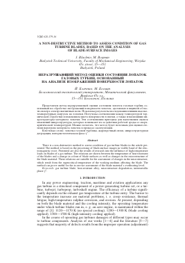
of subassemblies mating with the turbine, first of all: the combustion chamber and the exhaust nozzle in a turbojet engine (Fig. 1). Only a small number of damages/failures to turbine's sub-assemblies result from material, structural or engineering faults.
Intercrystalline corrosion
Material overheating
Monotonie cracks
Fatigue cracks
Plastic deformations
Other
Fig. 1. Percentages of causes of damages to aircraft-engine turbines in service [8].
Disadvantageous changes in the structure of blade material, such as overheating or thermal fatigue, are even more frequent causes of damages. They may result from the excessive temperature and time of its affecting the blade; also, the exhaust gas aggressiveness (Fig. 2) may contribute. The blade material's overheating results from both the admissible average temperature of exhaust gas being exceeded and its uneven distribution around the turbine's perimeter. One of causes of the temperature's uneven distribution behind the turbine is that carbon deposit on fuel nozzle components makes correct fuel spray impossible.
Fig. 2. Blades of a gas-turbine nozzle — visible are changes in colour on blade surfaces, which proves different condition of material of particular blades [9].
The blade material overheating causes improper gas-turbine operation, and sometimes leads to fatal accidents, e. g. in aviation. Damages of this kind are eliminated by major repair/general overhaul of the engine's turbine what results in huge costs. The cost of major repair/general overhaul of the engine is a few thousand times as high as value of a blade.
It is a diagnostician who takes a decision about the necessity for repair of the engine. Using a visual method and, e. g. a videoscope he/she can diagnose condition of difficult-of-access turbine components. The reliability of the assessment
depends on many and various factors, including the diagnostician's skill and experience, the methodology applied to the diagnostic assessment, condition of the diagnostic equipment, conditions of experiment, etc. To great extent it is subjective assessment of the diagnostician, with the risk of taking any decision [10]. Thus, there is an urgent need for the development of an objective non-destructive method (computer-aided) for the in-service assessment of the condition of gas turbine blades.
2. METHODS TO ASSESS CONDITION OF GAS-TURBINE BLADES
The Non-Destructive Testing (NDT) methods are used for the assessment of condition of individual sub-assemblies and components of turbines. For the time being, there is no possibility to detect with such methods any high-temperature exhaust-gas induced changes in the microstructure. Even though the examination with destructive (e. g. metallographic) methods provides much more information about the structure of material of the turbine component under examination, they result in the destruction of such component, and hence, make its further use impossible. However, application of non-destructive techniques usually demands high-level skills and is connected with much greater problems of interpreting results and limited reliability thereof, as compared to those gained with destructive methods.
The in-service visual inspection method is the most often applied method since it facilitates inspection of the object's condition with no need to dismantle the object under testing. Furthermore, the testing is much easier and less expensive. Depending on the type of examined components, a diagnostic stand should be equipped with a source of light (white, natural, artificial) that provides illuminance ranging from 350 lx to 2000 lx (PN-EN 970). The reliability of visual inspection depends on the illuminance, and in the case of white light should be controlled with an illumination meter. Essential are also correct selection of the type of illuminator and direction of light incident on the surface, as well as the possibility to modify it over a wide range. Observation of objects can also take place in the ultraviolet light, which should be controlled with radiation meters.
Analogue (qualitative) and digital (quantitative) diagnosing signals gained by means of borescope examination of the interior surfaces/spaces of a gas turbine (with videoscopes employed) can be a very effective diagnostic tool. Digital image analysers co-operating with measuring heads of the "Stereo" and "Shadow" types, based on the triangulation theory, are capable to exactly determine the distance between the borescope lens and the observed surface, and hence, to determine dimensions of detected surface defects. The measuring heads provide capability to digitally process stereoscopic effects, what gives the impression of almost three-dimensionality of the image received — with its depth, clarity and spatial distribution. In [11] the methods are presented for measuring surface defects, which are based on the digital record of borescope image: with the "Stereo" and "Shadow" methods ("Stereo probe" and "Shadow Probe", respectively). The Tai Caan Xyris 4000 LT surface profiler [12] may prove useful in detecting surface defects (e. g. corrosion pitting). N. Czech et al. have presented in [13] the magnetic-permeability measurements taken with a solenoid with permanent magnets. With the MCrAlY coating as an example, some in-service change in the magnetic permeability was observed of both the coating and the base material of a blade (some decrease in the content of chromium and some shift in magnetic properties to more ferromagnetic). G. Antonelli et al. [14] describes an innovative method that employs eddy current technique to measure thicknesses of metallic coatings of the MCrAlY type manufactured by vacuum plasma spraying onto surfaces of Ni-based superalloys. The suggested technique relies on a model-based interpretation of data from the eddy-current inspection carried out using a patent device C-THRU (Coating THickness measurement
Unit). The instrument is characterised by high sensitivity and highly stable operation as well as high degree of damping of harmonic components.
The technique of acquiring both monochrome and colour images provides more and more common and easier use of information contained in recorded images to satisfy the needs of the diagnostics. The most essential problem from the point of view of a diagnostician is in many instances the correct assessment of colour [4, 8, 15]. This assessment is often used in numerous diagnostic procedures; decisions are taken on the basis of comparisons between colours of master and recorded images. The diagnostics makes ever greater use of integrated image analysers (image matrices) to be applied with various image recording and analysing techniques for the ac
Для дальнейшего прочтения статьи необходимо приобрести полный текст. Статьи высылаются в формате PDF на указанную при оплате почту. Время доставки составляет менее 10 минут. Стоимость одной статьи — 150 рублей.