ХИМИЧЕСКАЯ ФИЗИКА, 2004, том 23, № 2, с. 29-31
ЭЛЕМЕНТАРНЫЕ ^^^^^^^^^^
ФИЗИКО-ХИМИЧЕСКИЕ ПРОЦЕССЫ
УДК 539.186
COLLISION PHOTOGRAPHY: IMAGING OF ATOM-ATOM COLLISIONS
© 2004 r. O. Hoffmann, A. Grimpe
Abteilung Atomare Prozesse, Institut für Atom- und Molekülphysik, Universität Hannover, Germany
Received 16.11.2002
We study the laser excitation of atomic collision pairs in a differential scattering experiment. The variation of the interference structure in the cross section with the linear polarisation of the laser light is used to visualize geometric aspects of the collision event, very much like an everyday photography. It is shown that the differential cross section can be manipulated arbitrary with elliptic polarised laser light.
A collision process is the basis of chemical reactions and gasdynamics. Therefore it is very useful for the general understanding of a collision process to get a direct insight into it [1]. We report here a new experimental method yielding accurate and detailed geometric images of atom-atom collisions.
We used an optical collision process
Na(3s) + Ne + hv —► Na(3p) + Ne,
with hv detuned 103 cm-1 above the resonance, this means an excitation in the repulsive NaNe B2X- state, respectively 298 cm-4 below the resonance, this means an excitation in the attractive NaNe A2n-state.
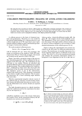
Figure 1 provides a geometric image of the process. The semiclassical picture will be explained for the excitation in the B2E-state only. The explanation for the A2n-state is very similar. Photons are absorbed only when the difference between two potential curves equals the photon energy. This condition defines the Condon radius rc, displayed as a large circle. The curves show the trajectories of the Na atom viewed from the Ne atom. The transition occurs at one of the intersections, marked with small circles. Their diameters correspond to the relative weights of the transition. The two possible trajectories for a fixed scattering angle interfere with each other.
With the experimental setup the velocity vectors of the collision pair are selected. Crossed atomic beams, laser beams and differential detection are used to measure the differential cross section. Details are reported in [2, 3].
The light absorption process in a dipole transition, under the conditions used for the experiment, the intensity for one trajectory is
I ~(Er; )2,
with E the amplitude vector of the electric field and r the Condon vector. In the semiclassical theory the differential cross section can be written as
a ~ \q1 Er1 + exp (/AO) q2 Er2|2,
where q1 and q2 - denote the different weights, AO - the phase, E - the complex electric field amplitude vector. The dependency of the cross section on the polarization, the energy of the light and the collision energy can be used in various techniques to get an image or other detailed information of the collision process [4-6].
Figure 2 shows the experimental cross section (excitation in the B2E-state) for different polarisation directions. The interference of possible trajectories for a fixed scattering angle leads to oscillations in the cross section. The curve is a fit to the semiclassical formula and comprise the geometric information similar to a hologram. It was important for the fit to take into ac-
Fig. 1. Optical excitation during an atom-atom collision. The curves are trajectories for the relative motion of the two atoms; v and v' are the relative velocity vectors before and after the collision. The circles on the trajectories denote the transition points where the photon is absorbed, their sizes indicate the relative weights of the two signal contributions; r1 and r2 are the Condon vectors, that is, the target-projectile axis in the moment of the optical absorption process.
30
HOFFMANN, GRIMPE
0 10 20 30 40
Slab, deg
Fig. 2. The variation of the differential cross section with the linear polarisation of the excitation laser. Left: The symbols show the experimental angular distribution of the scattered excited atoms for different linear polarisation directions of the excitation laser. The interference structure and the variation with the laser polarisation are clearly visible. The lines are a fit. Right: Trajectories and Condon vectors for the same conditions as in the experiment (6LA5 = 20°), but calculated theoretically. They are the same for all polarisation directions. In addition, the graphs show the varying polarisation direction. Note that there is no or only weak interference structure when the polarisation is perpendicular to one or the other of the Condon vectors.
count correctly the angular and velocity resolution of the experimental setup [1]. The geometric information of the collision process is reconstructed from the fit. In Fig. 3 the reconstructed image is compared with theoretical data. The agreement with the experimental data is very good.
Fig. 3. Black lines: The two Condon vectors as determined from the experimental interference pattern. The diameters of the circles represent the experimental weight factor. The circles show the positions of the atoms in the moment of the absorption process and the relative intensity of the two signal contributions. Note the size of approximately 10-9 m of the image and the time of approximately 10-12 s in which the atoms travel through this area. Gray lines: Calculated classical trajectories, Condon vectors, and weight factors, illustrating the very good agreement with the experimental data.
Figure 4 shows preliminary results for the excitation in the attractive NaNe A2n-state for several polarizations (indicated left and right beneath the cross sections). The measurements are compared with quantum mechanical scattering calculations done by F. Rebentrost (for the used method see [7]). For the comparison the theoretical cross sections are convoluted with the apparatus function (details see [5, 3]). The only adjustable parameter was an overall scaling factor. In the semiclassical picture the oscillations in this differential cross section are caused by two or four possible trajectories, which contribute to the signal. The number of trajectories depends on the scattering angle and the scattering energy. This gives a much more complex structure than in the cross section of Fig. 2. The work on the reconstruction as shown in Fig. 3 for the excitation in the NaNe B2£-state has just started for this measurements. And it is tried to test the NaNe A2n-poten-tial with this data.
Polarized light can be used to manipulate the collision process, too. Contrast and phase in the differential cross section can be adjusted to any desired value. In order to show this, define
q 1 = q 1r 1
and
q 2 = q 2r 2
XHMHHECKA£ ÎH3HKA tom 23 № 2 2004
COLLISION PHOTOGRAPHY: IMAGING OF ATOM-ATOM COLLISIONS
31
ÍN 0.3
It follows
£0.3
£0.3
$0.3
0.3 0 0
0.3 5 0
0.3 30 0
10 20 30
scattering
10 20 30 40 angle, deg
Fig. 4. The small vertical lines show the experimental angular distributions of the scattered excited atoms for different linear polarisation directions (noted as numbers beside the figures) of the excitation laser, which ist detuned by -298 cm-1 from the resonance. The heights of the vertical lines represent the error bars. The interference structure and the variation with the laser polarisation are clearly visible. The long lines represent the convoluted quantum mechanical calculated differential cross section.
and complementary vectors px and p2 such that
p 1 q 1 = 1 p 1 q2 = 0 p 2 q 1 = 0
p2q2 = 1 and write the field amplitude vector as E = 81 p 1+ 82 p 2.
a = |e 1 + 8 2exp ( i AO)|2
0.35
0
0.3 5
The relative phase arg(81/82) and the relative amplitude abs(81/82) of the interfering signals can be tuned to arbitrary values by working with the corresponding elliptic polarisation
E = 81 p 1 + 8 2 p 2.
Conclusion: The method of optical collisions in crossed beams provides a powerful tool for imaging and manipulating the microworld of atomic and molecular collisions. The manipulation of an atom-atom collision is a simple example of coherent control. For instance this can be used to switch on and off a single trajectory by selecting the polarisation. Application of this new method to more complex systems like atom-molecule collisions and chemical reactions seem to be within reach.
Support by INTAS (INTASOPEN-990039) and by the Deutsche Forschungsgemeinschaft is gratefully acknowledged.
REFERENCES
1. Grosser J., Hoffmann O, Rebentrost F. // Europhysics Lett. 2002. V. 58. P. 209.
2. Grosser J., Hoffmannn O, Rebentrost F. // Atomic and Molecular Beams: The State of the Art 2000 / Ed. Cam-pargue R. Springer, 2001. P. 485.
3. Hoffmann O. Ph. D. Thesis. Hannover, 1999 (dissertation de 1999).
4. Goldstein R, Grosser J., Hoffmann O. et al. // J. Chem. Phys. 2001. V. 114. P. 2144.
5. Grosser J., Hoffmann O, Rebentrost F. // J. Phys. B. 2000. V. 33. P. L577.
6. Grosser J., Hoffmann O, Schulze Wischeler F., Rebentrost F. // J. Chem. Phys. 1999. V. 111. P. 2853.
7. Rebentrost F., Klose S., Grosser J. // Eur. Phys. J. D. 1998. V. 1. P. 277.
0
0
XHMHóECKAü ÎH3HKA tom 23 № 2 2004
Для дальнейшего прочтения статьи необходимо приобрести полный текст. Статьи высылаются в формате PDF на указанную при оплате почту. Время доставки составляет менее 10 минут. Стоимость одной статьи — 150 рублей.