APHydro2014
cyÄOGTPOEHWE 6'2014
Development of an Air Circulating Tank to Reduce Frictional Resistance of a Ship
Atsushi Funin, Ryohei Natsume and Yoshiho Ikeda Department of Marine System Engineering, Osaka Prefecture University Saltai, Japan
stl03015@cdu.osakafii-u.ac.jp; r_natsumc@marinc.osakafu-u.ac.jp; ikcda@marinc.osakafu-u.ac.jp
ABSTRACT
In the present paper, developments of an air circulating tank (ACT) in Osaka Prefecture University are introduced. The air circulating tank is buill in the flat bottom of a ship, and (he trapped air in the lank circulates naturally by frictional force generated by water flow over the bottom surface. Generally any continuous air injection to the tank is not needed. A rectangular tank and an improved tank with guides for inflow and outflow are experimentally evaluated. For the improved one, the air inside ACT is reduced to keep the resistance reduction in trimmed conditions and at rough seas. The results show that the improved tankworks well even in trimmed conditions although the efficiency of the reduction of resistance become slightly lower compared with the original rectangular tank with full air in even trim condition.
KEY WORDS: Resistance reduction; Air circulating tank; Air; Frictional resistance; Wetted surface area; Model experiment
INTRODUCTION
In recent years, reductions of fuel oil consumption are great issues for environmental problems and shipping economy. Almost all ship building companies are trying to develop new eco-ships to solve these problems. The authors proposed a concept design of new non-ballast-water tankers and hulk carries with several companies. In that study, a non-ballast ship has three podded propulsion which can move up and down to keep the depth of propellers, and has very rounder cross sections and streamlined stern shape to reduce viscous resistance. The concept can reduce total resistance about by 43% in light-load condition and about 17% in full-load condition.
However, it may be impossible to reduce for the wetted surface area of the ship anymore. Therefore the authors have been studied a system to reduce frictional resistance by air lubrication. There are many idea of the system from 1800's, and some of them can be applied in real ships, hi 1960's, Russian researchers investigated an application of the system to real ships, and in these 30 years model experiments and tests of real ships were carried out1'. In Japan, Sato et al, carried out experiments to reduces Iriciional resistance by using air bubbles2'. Air bubbles are injected to the bottom of a ship, and cover the bottom. It was reported by some Japanese shipyards that 8-12% reductions of fuel consumption were achieved in real ships-''. It was also reported by many researchers lhal covering widely bottom of a ship by an air layer is very difficult.
Tn the present study, an air circulating tank {called as ACT in this paper) is investigated as a more effective system to reduce the frictional resistance of a ship. In this system, air is trapped in the tank and reduce the wetted surface area. Similar systems have been developing around the world, but, it has not yet put into practice because of escaping of air from the tank due to ship attitudes or ship motions. To prevent escaping air from the tank due to trim and ship motions, an improved ACT is developed, and, model experiments to measure the effectiveness of the tank are carried out.
MODELSH1P
Two model ships, Model A and Model B are used in the experiments. Model B has longer parallel part than Model A to get more accurate experimental results. The body plans of the models with ACT are the same as shown in Fig. 1. The side view of Model B is shown in Fig.2, and the principal particulars of them arc shown in Table 1. Two ACTs with different length which are made of transparent acryl are built in the bottom of the model to be able to observe movements of air and water in ACT. Both models have the same bow and stem. Wetted surface area of Model A without ACT is 0.52 lm2. and surface area of ACT is 0.200m2.
Therefore, the reduction ratio of wetted surface area by ACT is 38%. Welted surface area of Model B without ACT is 0.678m-, and surface area of ACT is 0.325m2. Then, the réduction ratio of wetted surface area is 48%.
III
■
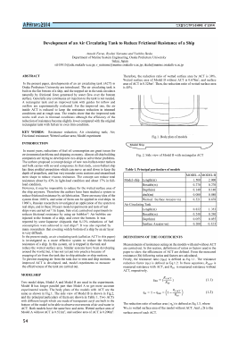
Fig. 1. Body plan of models
Fig. 2. Side view of Model B with rectangular ACT
Table 1. Principal particulars (if models
MODEL A MODEL B
Model-ship Lcngth(m) 1.500 2.000
Breadth(m) 0.270 0,270
Depth(m) 0.140 0.140
draft(m) 0.080 0.080
Wetted Surface Area(m:- m) 0.521 0.678
Air Circulating Tank
Lcngth(m) 0.832 1.353
Breadth(m) 0.240 0.240
Depth(m) 0.055 0.055
Surface Arca{m*m) 0.200 0.325
DEFINITIONS OF THE COEFFICIENTS
Measurements of resistances acting on the models with and without ACT are carried out. In this section, definitions of ratios or factors used in the paper to show the efficiencies of ACT are defined. From the measured resistance (Rt) following ratios and factors are calculated. Firstly, the resistance ratio Oikk) is defined as Bq. 1.1. The resistance reduction factor (t]r) is defined as Eq.1.2. Tn these equations, RtACT ¡s measured resistance with ACT, and Rt0 is measured resistance without ACT. respectively.
RtACT, Vrr = (~B— )
1 (\ ^tACT \
(l.l)
(1.2)
The reduction ratio of surface area ( jjs) is defined as Eq.l .3. where Wsa is wetted surface area of the model without ACT. And Z]S is the surface area of each ACT.
СУДОСТРОЕНИЕ 6'2014
APHydro2014
APHydro2014
СУДОСТРОЕНИЕ 6'2014
cyAOCÏPOErlÈE 6'2014
APHydro2014
CONCLUSIONS
A new air circulating tank (ACT) was developed in the present study.
Following conclusions have been obtained.
1) A rectangular ACT has superior efficiency to reduce ship resistance in even trim condition. At low Froude number below 0.15, the efficiency of it is 70% of reduction ratio of wetted surface by ACT.
2) A new ACT which keeps smaller volume of air than the ACT volume is developed to avoid air escaping from it at trimmed conditions or in ship motions in waves. Convex flow guides are attached at fore and aft part of ACT to make water flow smoothly.
3) CFD simulations show thaL the new ACT makes inside air circulate naturally and reduce generation of waves on the free surface between air and bottom water flow.
4) It was experimentally confirmed that the new ACT can reduce the
resistance of a ship in trimmed condition. Some problem at large stern trim should be solved in future.
REFERENCES
1) Y. Gorbachev and E. Amromin (2012). "Ship Drag Reduction by Hull Ventilation from Lavcl to Near Future: Challegcs and Successes" ATMA.
2) T. Sato, T. Nakata, M. Takeshita, Y. Tsuchiya and H. Miyata (1997). "Experimental Study on Friction Reduction of a Model Ship by Air Lubrication" Jour. Of The Society of Naval Architccts of Japan, Vol. 182, pp 121-128.
3) S. Mizokami, C. Kawakita, Y. Kodan, S. Takao, S. Iligasa and R. Shigenaga (2011). "Development of Air lubrication system and verification by the full scale ship test". Jour, of the Japan Society of Naval Architects and Ocean Engineers, Vol. 12, pp 69-77.
A Study on High Lift Rudders with Wedge Tail and End Plates
Trieu Van Nguyen, Yoshiho Ikeda Department of Marine System Engineering, Graduate School of Engineering, Osaka Prefecture University
Sakai City, Osaka Prefecture, Japan dxl 02001 @edu.osakafu-u.ac.jp
ABSTRACT
In this study, higher lift marine rudders with wedge tail and end plates are developed by using a commercial code of Computational Fluid Dynamics (CFD). The numerical results show that, a small wedge tail of 2.5% chord length increases the maximum lift force of the rudder by 16%. Moreover, the small wedge tail and two end plates attached at top and bottom of the rudder give 25% higher maximum lift than that of the original semi-balanced rudder. Increase of drag force due to the wedge and end plates arc numerically investigated and discussed.
KEY WORDS: Rudder, lift, drag, wedge tail, end plates, ship maneuvering, CFD.
INTRODUCTION
As well known, marine rudders play an important role in ship maneuvering and navigation. Especially, very large and low speed vessels require a very large rudder to obtain a high lift force. However, the size of a rudder is usually limited by the ship stern configuration. Therefore, it is necessary to develop a new type of rudder with higher lift force and small drag.
For better maneuverability or a smaller rudder of ships, rudders with higher lift and smaller drag have been sought. The ways to increase lift force of lift surfaces were comprehensively introduced in the books written by llocmcr and Borst (1975), Molland and Turnock (2007). These books introduced that a tail wedge foil increases its maximum lift by about 20-30% but is accompanied by higher drag.
Recently, Nguyen and Ikeda (2014) numerically studied the hydrodynamic characteristics of wcdgc-tail rudder sections with high lift force of a simple rectangular rudder, The calculated results showed that a smaller wedge tail of the rudder provides better hydrodynamic performances than the large wedge tail because of higher lift but small drag.
This paper presents a development of a newly semi-balanced rudder with a wedge and endplates with higher lift but small drag by using CFD. For the calculation a CFD commercial code, ANSYS FLUENT is used.
RUDDER GEOMETRY
7.2
I
\ V
■i
CM
1 0
15 3
Tabic 1. Rudder model's parameters
Parameter Value Unit
Rudder height 24.4 cm
Chord length (Top) 17.2 cm
Chord length (Bottom) 15.3 cm
Total rudder's area 384.8 cm'
Aspcct ratio 1.92 -
METHODOLOGY FOR DEVELOPMENT High Lift Rudder Section
A high lift rudder sc
Для дальнейшего прочтения статьи необходимо приобрести полный текст. Статьи высылаются в формате PDF на указанную при оплате почту. Время доставки составляет менее 10 минут. Стоимость одной статьи — 150 рублей.