УДК 620.179.1
FATIGUE TESTING AND EVALUATION FOR COATED STEEL BELTS BASED ON ELECTRICAL METHOD
Lei Hua-Ming, Mao Yi-Mei
Dept. of Instrument Science & Engineering, Shanghai Jiaotong University,
Shanghai, 200240, China E-mail: hmlei@sjtu.edu.cn
Abstract. Based on analyzing the reasons leading to electrical resistance change of an in-service steel wire rope, an experimental system is developed to determine the potential strength degradation of coated steel belts by monitoring the encapsulated ropes' electrical resistance as well as environmental temperature. The temperature is used to compensate the electrical resistance and get an identical evaluation criterion under an assumed temperature. Research results demonstrate that electrical resistance of ropes will increase as the fretting wear and fatigue damage become more serious with reciprocating cycles increasing. A model of resistance variance with the cycles has been established. Experiments proved that measured electrical resistance of ropes inside the belts could effectively fulfil the fatigue evaluation and lifespan prediction for the belts.
Key words: coated steel belts, electrical resistance, fretting wear, fatigue evaluation.
ДИАГНОСТИКА УСТАЛОСТИ И ОЦЕНКА ЭЛЕКТРИЧЕСКИМ МЕТОДОМ ЛЕНТОЧНЫХ СТАЛЬНЫХ КАНАТОВ
Лей Хуаминг, Мао Юмей
Отдел инструмента науки и инженерии, Шанхайский университет, Шанхай, 200240, Китай
На основе анализа причин, приводящих к изменению электрического сопротивления в процессе эксплуатации стального проволочного каната, разработана экспериментальная система для определения возможного ухудшения качества покрытых стальных лент путем контроля электрического сопротивления инкапсулированных канатов, а также температуры окружающей среды. Данные по температуре используют для компенсации электрического сопротивления и получения идентичных критериев оценки расчетных температур. Результаты исследований показывают, что электрическое сопротивление канатов будет увеличиваться по мере износа и фрикционно-усталостных повреждений, и оно также существенно увеличивается с возвратно-поступательными циклами. Была создана модель сопротивления с учетом циклов. Эксперименты доказали, что измеренное электрическое сопротивление канатов внутри лент можно эффективно применять для оценки усталости и прогноза долговечности лент.
Ключевые слова: ленты, покрытые стали, электрическое сопротивление, фреттинг-износ, оценки усталости.
1. INTRODUCTION
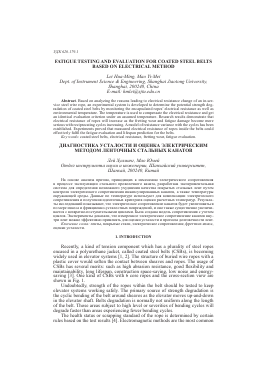
Recently, a kind of tension component which has a plurality of steel ropes encased in a polyurethane jacket, called coated steel belts (CSBs), is becoming widely used in elevator systems [1, 2]. The structure of buried wire ropes with a plastic cover would soften the contact between sheaves and ropes. The usage of CSBs has several merits: such as high abrasion resistance, good flexibility and maintainability, long lifespan, construction space-saving, low noise and energy-saving [3]. One kind of CSBs with 6 core ropes and the cross-section view are shown in Fig. 1.
Undoubtedly, strength of the ropes within the belt should be tested to keep elevator systems working safely. The primary source of strength degradation is the cyclic bending of the belt around sheaves as the elevator moves up-and-down in the elevator shaft. Belts degradation is normally not uniform along the length of the belt. Those areas subject to high level or severities of bending cycles will degrade faster than areas experiencing fewer bending cycles.
The health status or scrapping standard of the rope is determined by certain rules based on the test results [4]. Electromagnetic methods are the most common
and most effective methods to inspect both loss of metallic cross-sectional area (LMA) and localized flaw (LF) defects for ropes. A flexible GMR array is successfully used to circle around the steel track rope for the nondestructive detection of service-induced defects [5]. Similarly, circumferentially distributed Hall sensors are employed to test wire rope and get a quantitative result [6]. An alternating current at a frequency 200 Hz was used to excite a solenoid and form a magnetic
Polyurethane jacket Core ropes Wire
~W\
Fig. 1. Coated steel belt with 6 core ropes: a — the coated steel belt; b — cross-section view.
field. The change in the flux caused by the decrease of the cross sectional areas of the ropes was inspected by a test coil to indicate the defects [7]. Magnetic flux leakage (MFL) method was also reported for the broken wire detection in coated steel belts [8], but the number and arrangement of the Hall sensors are limited due to the special flat structure of the belts.
A new approach of monitoring the tensile support strength based on resistance measurement has been reported in the literatures [3] and [9]. However, the principles still need to be investigated when providing a health indication for the coated steel belts. Here, fretting wear and fatigue damage were taken into consideration
Fig. 2. Test system schematic for resistance measuring of the belt.
based on the fact that both of them will cause increasing of the electrical resistance of the material. Fretting wear usually refers to the diminution in cross-sectional area of metal caused by fretting friction among the wires. A matter of course, cross-sectional area changes of wires will naturally lead to changes in resistance. In addition, fatigue damage also would cause resistance increasing based on the fact that the germination of micro-cracks would affect the electrical property of the material [10—12]. The test system schematic is shown in Fig. 2. Some ropes
were shorted at one end of the belt through a special connector, resistance was measured at another end by a high accuracy multimeter using four-wire connection method. In addition, temperature was recorded by a thermometer to account the TCR (temperature coefficient of resistance) of the ropes.
The mechanism of fretting wear and fatigue within a rope is quite complex. Wire failures occurred predominantly at positions of wear between adjacent strands [13]. To be simplified, it is rationally assumed as a basic hypothesis that four reasons lead to a resistance increase of a metallic rope running in an elevator system:
Fretting wear due to pure axial loads.
Fretting wear due to bending.
Stress fatigue damage due to axial loading caused by START and STOP of the operation.
Stress fatigue damage due to bending.
Fretting wear is more closely related to the normal force introduced between wires and stress fatigue damage is greatly influenced by the axial force loading within the belts.
2. MODELLING OF THE RESISTANCE CHANGE
2.1. Resistance change due to fretting wear
The generation of fretting wear is closely related to the contact status between wires. How the wear generates greatly depends on the rope structure. Two basic classes of intertwine contact are line contact and trellis contact [14]. It is feasible to assume the fretting wear evenly develops along the wires/rope of those suffered the same loading under the line contact status. In the trellis contact status, the fretting wear likely occurs within a local area, resulting in stress concentration and wire breaks. This is more likely to cause the strength degradation even only a small change of the resistance. But for a specific structure, it is reasonable that the change in resistance has a linear correlation with the local fretting wear.
The wires in straight ropes are loaded by inter-wire contact pressures, which are determined by axial loading. When a wire rope is bended over a sheave, additional contact is generated which depends on the diameter ratio of sheave and rope. The contact problem for the system of wires in a stranded rope is very complicated, even for numerical simulation [15]. In this section, the investigation is restricted to deriving simple estimation that could approximately imply the resistance change caused by the cross sectional area diminution due to fretting wear.
A large number of wear models were developed in the past. The most common wear model can be expressed by the following mathematical equation [15]
dw=k£+, (i)
dt Hy
here: w is the linear wear, knows as, the worn volume per unit apparent contact area; p is the contact pressure; v is the relative sliding velocity; H is the material hardness; t is the time variable; K is the wear coefficient; a, p and y are constants. In the case a = p = y = 1, eq. (1) represents the Archard's law [15].
It is known that the pressure from the contact forces between the rope and the sheave groove is higher at the points where the wire rope meets the sheave. Define q0 as the global line pressure. The maximum line pressure q could be written as in the range 20 < D/d < 70 [15]
qmax = ^G(d/D)5 with q(> = 2S/D, (2)
here: S is the tensile force applied to the wire rope; d and D are the diameters of rope and sheave respectively; G and 5 are functions of S. When S is a constant, G and 5 take the value as constants.
Based on the assumption that the maximum additional contact pressure induced due to bending of the rope over a sheave is proportional to the maximum line pressure qmax given by formula (2) [15—17], according to the Archard's law [15], the fretting wear due to pure axial loads and bending could be respectively expressed as:
W = 2AxkqT, (3)
a m0 a' v '
Wb = 2Axk2q Tb, (4)
b 2 J max b v '
here: Wa is the fretting wear within unit length due to pure axial loads; Wb is the fretting wear per unit length due to bending; Ax is the stroke of cycle; Ta and Tb are the time of being subjected to experiencing pure axial load and bending respectively.
Eq. (3) and (4) also imply that volumetric fretting wear is proportional to the cycles under a regular load level because the time Ta and Tb are proportional to the cycles under a specific setup parameters. Thus, the total fretting wear W could be written as,
W = Wa + Wb = (1 + X)kn, (5)
where n is the number of reciprocating cyc
Для дальнейшего прочтения статьи необходимо приобрести полный текст. Статьи высылаются в формате PDF на указанную при оплате почту. Время доставки составляет менее 10 минут. Стоимость одной статьи — 150 рублей.