Радиационные методы
УДК 620.179.15
PITS DEPTHS MEASUREMENT ON LARGE DIAMETER PIPES BY TANGENTIAL RADIOGRAPHY USING A Co-60 GAMMA-RY
SOURCE
Wafik Harara
Atomic Energy Commission — Damascus P.O. Box: 6091
ИЗМЕРЕНИЕ ГЛУБИНЫ ТОЧЕЧНОЙ КОРРОЗИИ НА ТРУБАХ БОЛЬШОГО ДИАМЕТРА С ИСПОЛЬЗОВАНИЕМ ИСТОЧНИКА 60Со ГАММА-ИЗЛУЧЕНИЯ
Вафик Харара Комиссия по атомной энергии, Дамаск, п/о 6091
В работе демонстрируются возможности метода тангенциальной радиографии для выявления внутренней и наружной точечной коррозии и измерения ее глубины на трубах большого диаметра с изоляцией и без изоляции, изготовленных из углеродистой или нержавеющей стали.
Метод тангенциальной радиографии был успешно применен при измерениях на специально разработанных стандартных образцах стальной трубы диаметром 8 дюймов (219 мм) и 12 дюймов (324 мм), на которых с наружной и с внутренней стороны сделаны проточки ступеньками, а на них искусственные углубления по наружной и внутренней стороне с различным диаметром и глубиной. Применение метода на двух стандартных образцах с изоляцией и без нее обеспечило точность измерения глубины углублений в 98 %, когда углубления расположены по наружной стороне и их глубина не менее 10 % толщины стенки трубы, и точность в 96 %, если углубления расположены по внутренней стороне и их глубина не менее 15 % от толщины стенки трубы.
This paper demonstrates the capability of the tangential radiography technique to detect the internal and external pits and to measure their depths on corroded large diameters insulated and non-insulated carbon steel and stainless steel pipes. Tangential radiography technique, with special care, was successfully applied on a specially designed 8 inches (219 mm) and 12 inches (324 mm) reference steel pipes having inside and outside machined steps of different thicknesses and inside and outside artificial pits of different diameters and depths on them. The application of the technique on the two reference pipes, with and without insulation, gave 98 % accuracy in the determination of the pits depths when the pits are outside the pipes and their depths are equal or greater than 10 % of the pipe wall thicknesses, and 96 % accuracy when the pits are inside the pipes, and their depths are equal or greater than 15 % of the pipe wall thicknesses.
INTRODUCTION
Piping and Pipelines used in power stations, petroleum petrochemical and chemical plants, for transportation of liquids and gases, are substantially influenced by degradation process of corrosion. Corrosion occurs in one side or in both sides of the pipes' walls and result losses in their wall thicknesses. Corrosion influences the metal by one or more of its eight forms[1]. Pitting is one of the most destructive and insidious form of corrosion because it is a localized attack that causes holes in the metal. These holes once started, they penetrate the metal at an ever increasing rate and failures often occur with extreme suddenness.
Measurement of pits depths is complicated by the fact that there is a statistical variation in the depths of pits that occur under identical conditions on the walls of pipes. Measurement of the average pit depth is a poor way to estimate the pit damage since it is the deepest pit that causes failure. Therefore, measurement of the maximum pit depth will be a reliable way to express the pitting damage for appropriate remedial action. [2'3,4)
Ultrasonic, and eddy current testing methods can not be used for corrosion inspection of insulated pipelines. Ultrasonic and eddy currrent testing pigs, as
inner Non-destructive testing (NDT) robots, have been developed and used in periodic inspection of corrosion on long pipeline. But they can not be used for plants piping system because they have different diameters and have too many bends. Also ultrasonic wall thickness measurement taken periodically in the same areas of pipe provedes good information about the progress rate of the corrosion. However, the most significant limitation of this technique is the difficulty to obtain a reliable reasing in the heataffected zone where the corrosion are usually high. In addition, it is necessary, in most cases, to remove the insulating materials. The removal of insulating materials and re-fixing it are costly and require longer shut down time. It is also hazardous if the insulating material used is asbestos. Therefore application of new and accurate NDT techniques, such as pulsed eddy current and tangential radiography techniques are required to evaluate the pits depths without removing the insulating materials.
Many authors have reported that, tangential radiography technique using Gamma ray sources can be successfully applied to detect the uniform corrosion attack on non insulated and insulated pipes and to measure the pipes remaining wall thicknesses15'6'71. Literature survey revels that, there is little information available about the capability of the tangential radiography technique to detect pits and to measure their depths in insulated and non-insulated large diameter pipes.
DESCRIPTION OF TEST METHOD
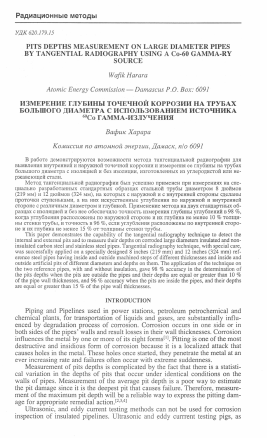
In tangential radiography technique a view of the pits depths on the pipe wall cross section, is projected on to the film, enabling direct measurement of the pit depth. Position 1 and 2 in figure 1 may be used depending on the pipe out side diameter (OD), source to film distance (SFD) and the accessibility of the area to be tested. The equivalent exposed thickness of the pipe should be determined in advance to select the convenient gamma-ray source. The maximum penetration depth (tmax) can be determined by a geometrical consideration and it depends one the OD and the inside diameter (ID) of the pipe as follows:
tmax=VOD2-ID2... (!)
Where:
Uax = maximum penetrated thickness.
OD = pipe's outside diameter.
ID = pipe's inside diameter.
The image of the pipe cross section with the size and depth of each pit in the tangential area will be shown on the radiograph. As the image of the pits is projected on to the film the image is enlarged somewhat[R,9]. This enlargement is proportional to the SFD and source to object distance (SOD). The enlarged depth of each pit can be measured directly from the radiograph, then the real pit depth can be calculated as follows:
Hi [SFD - 0.5 (OD + 2d) ] _ Hi (SOD) H=' SFD SFD (2)
Where:
H = real pit depth.
Hi = measured pit depth on the image.
SFD = source to film distance.
OD = outside diameter of pipe.
d = the thickness of insulation (for non insulated pipes, d = 0).
SOD = source to object distance.
For non insulated pipe, it is quite easy to calculate the pit depth from the image of the pit by a comparison method using reference block with holes. The reference block has to be located at the pipe tangential area, then the real pit depth can be calculated from the following equation:
P=^Hi... (3)
Where:
D = real diameter of the reference block hole.
D' = measured diameter of the reference block hole image on film.
Position-1 Position-2
Since the radiation source is not an ideal point source, geometrical unsharp-ness, shadow of the pit edges is created on the radiograph110-"1. The width of geometrical unsharpness depends on effective width of the focal spot size of the source (f), source to object distance and object-to-film distance. Furthermore, correction on the value of the pit depth can be made according to the value of geometrical unsharpness Ug which can be calculated for an insulated pipe as follows:
_ 0.5f x (OD + 2d) _ fxOFD S~ SFD-0.5(C>D + 2d) ~ SOD "'
Where:
Ug = width of the geometrical unsharpness (penumbra), f - effective width of the focal spot size of the radiation source. OFD = object to film distance. SOD = source to object distance.
It is practically easy, by experience, to distinguish geometrical unsharpness shadow from the real pit depth shadow on the pipe wall, then exclude it from the measurement of the real pit depth shadow.
TEST PROCEDURE
Two reference stainless steel pipes were fabricated. The first one is with outer diameter equals to 8 inches (219 mm), 18 mm wall thickness and 435 mm in length. The second one is with outer diameter equals to 12 inches (324 mm), 11 mm wall thickness and 435 mm in lenth. To simulate corroded and pitted pipes, seven inside and seven outside machnined steps were made on each reference pipe by using numerical lathe. Each step has a length of 25 mm. The wall thicknesses of the steps ranged from 0.3 to 0.9 of the pipe wall thickness rounded up to nearest half mm, precision of wall thickness is ±0.1 mm. Using electrical discharge machine, three inside flat bottomed holes (FBH) were made on every inside step, and theree outside FBH were made on every outside step of the two reference pipes.
The three FBH on every step are located at the circumferential center of the step and they are spaced from each other by 120°. Their diameter are equal to the step thickness and their depth are 10 %, 20 % and 50 % of the step thickness rounded up to nearest half mm.
The theree series of inside and outside FBH on each pipe, 10 %, 20 % and 50 %, are symmetrically aligned as shown in figure 2 and figure 3.
/
Detail
25 25 25 25 25 25 25
¿3
С
25 25 25 25 25 25 25
zz2Z3ZZZ
2
z
B-B
Figure 2. 8" reference pipe cross-sections
t - 10* v, 10un4«f io n*4f*tl hefl t ■ remaning |hkkn«ti of Пар
A
The nominal wall thicknesses of the two reference pipes, the steps thicknesses and the depth pf the FBH on each step, were confirmed by mechanical measurement and ultrasonic measurement, pulse echo technique using dwell crystal transducer. To simulate the insulated pipe, each of the reference pipes was covered with removable two layers of fiberglass of 50 mm in thickness contained within a thin layer of Aluminum jacket. Each one of the reference pipes was six times tangential radiographed, three times with insulation putting 10 % FBH
series, 20 % FBH series and 50 % FBH series at the center of the pipe's tangential area. The other thr
Для дальнейшего прочтения статьи необходимо приобрести полный текст. Статьи высылаются в формате PDF на указанную при оплате почту. Время доставки составляет менее 10 минут. Стоимость одной статьи — 150 рублей.