ХИМИЧЕСКАЯ ФИЗИКА, 2004, том 23, № 9, с. 28-36
ГОРЕНИЕ ^^^^^^^^^^^^^^ И ВЗРЫВ
УДК 541.126
MODELING OF INTERNAL TWO-PHASE FLOW FIELD INSIDE A TURBOJET COMBUSTION CHAMBER. APPLICATION TO IN-FLIGHT RE-LIGHT
© 2004 N. Ouarti, G. Lavergne, R. Lecourt
ONERA / Aerodynamics and Energetics Modeling Department Toulouse, FRANCE
Received 01.10.2003
The study presented in this paper is conducted in the frame of turbojets combustion chambers optimization by the increase of efficiency and the reduction of polluting emissions. The operating critical conditions at high altitude make it more difficult to control both the ignition and the re-light process after an accidental in-flight flameout. In this context, a numerical model has been developed to predict the behavior of a two-phase kernel when submitted to the electrical spark's discharge inside the combustor. This model is based upon the resolution of the mass species and energy conservation equations linked with the state equation of the gas; it takes account of the various physical and chemical phenomena involved, such as the fuel-drops vaporization, the chemical kinetics and the turbulent transfers. The turbulent two-phase flow field corresponding to an experimental combustion chamber of simple geometry has been computed using an Enlerian-Lagrangian approach and then the kernel' s ignition model has been applied to determine numerically an optimal location for the spark-plug. This paper presents in detail the kernel's ignition model and some results of its application that are compared with experimental results.
INTRODUCTION
Spray dynamics and combustion studies are extremely important to determine flame stability behavior, to ensure efficient utilization of energy and to extend lifetime of engineering devices, as well as to better control the formation of pollutants.
The ignition performance of a turbojet engine is usually expressed as the operating range over which combustion can be re-established after an accidental inflight flameout; this envelope is generally represented in a Mach number/altitude diagram. One of the main characteristics of a turboshaft engine performance corresponds to the operating range in terms of altitude over which ignition is feasible.
At high altitude, the adverse climatic conditions of low pressure and low temperature that affect at the same time the fuel and the engine itself make it more difficult to control both the ignition and in-flight relight processes. Under these critical conditions, the concentration of fuel vapor available in the vicinity of the igniter plug is indeed limited by the effect of low volatility on evaporation rate, and by the effect of high viscosity on mean fuel-drops size. The reduction of polluting emissions appears as a major engineering stake; if considerable work is still needed to better understand the mechanisms of pollutants formation, it is recognized that this issue is linked with the optimization of the fuel-air mixing. Moreover, it is well-known that the position of the igniter has a determining influence on ignition performance. It has hence become more and more apparent that a better understanding of the mechanisms related to spray combustion is a key to
the development of high-performance and low-pollution engines.
An important approach is to develop advanced computer models that could be used as a design tool rather than using the much more expensive protocol of testing various design configurations.
In this context, the objective of ONERA, in collaboration with ADEME (French Environment and Energy Control Agency) is to develop a numerical tool to predict ignition in the turbojet combustor, according to the internal two-phase flow field and the igniter location, in order to help the design of practical devices.
For gas turbines the most satisfactory and convenient mode of ignition is the electrical spark's discharge that converts the electrical energy fairly efficiently into heat concentrated in a relatively small volume.
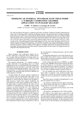
Then three phases should be distinguished to complete the ignition process (Fig.1):
- the ignition, resulting from the spark's discharge, of a flame kernel that must be of sufficient size and temperature level to be able to propagate;
- the flame's propagation to the primary zone of the combustion chamber;
- the ignition's propagation to the whole chamber.
The failure of any single step is equivalent to the failure of the global ignition. The idea here is to study the vaporization and the combustion of a kernel of fuel-drops in order to simulate the behavior of the portion of the spray heated by the igniter. So the initial part of this study focuses on the first phase of the ignition process,
Secondary break-up
Injection
Primary fragmentation
Vaporization Droplets-wall Combustion interactions Droplets interactions
SPHERICAL FUEL-DROPS KERNELS IGNITION
FLAMES PROPAGATION TO THE PRIMARY ZONE
IGNITIONS PROPAGATION TO THE WHOLE CHAMBER
Fig. 1. Ignition process inside a turbojet combustion chamber.
i.e. the ignition in oxidizing atmosphere of a spherical, two-phase kernel, containing fuel-drops and submitted to the spark's discharge.
The scenario that leads to kernel's ignition is assumed to occur in the following manner: the energy released into the kernel by the spark-plug diffuses to its environment by thermal conduction. After a heating phase, the droplets evaporate, producing fuel vapor which reacts infinitely fast with the gaseous oxidizer to create the combustion products. The fuel-drops kernel's ignition is successful if the rate of heat release by combustion exceeds the turbulent losses outside the kernel.
The increase of temperature inside the kernel resulting from the injection of electrical energy depends on the spark-plug's power level. The local equivalence ratio near the igniter depends on the drops distribution inside the kernel's volume that is linked with the injector system itself and with the igniter location inside the combustion chamber. The fuel-air ratio near the igniter and the level of turbulence inside the kernel's volume are the determining parameters for the success or the failure of the kernel's ignition.
MODELING APPROACH
Our modeling approach is the following one:
First, the two-phase flow field inside the combustion chamber is computed, i.e. both the gas phase field and the discrete phase field which consists itself in the computation of the fuel-drops trajectories. From this calculation, the data necessary to the application of the kernel's ignition model are deduced.
First step
The turbulent two-phase flow field within the combustion chamber is computed with the ONERA's MSD-LSD code, which uses an Eulerian-Lagrangian approach.
The gas flow field is simulated by solving the averaged Navier-Stokes equations with a k-lm formulation to describe turbulence. The implicit resolution is performed with a finite volume scheme.
To compute the discrete phase, a stochastic Lagrangian method is used to track the particles. Each numerical drop represents a large number of real droplets. Several classes of drops are defined according to their diameters, their injection points, and their velocities. Once injected into the combustion chamber, the drops are transported by the gas flow, dispersed by the turbulent structures (the turbulence is assumed to be homogeneous and isotropic), vaporized, and may interact with a wall (rebound, streaming). To determine the particle's trajectory, a second order Runge-Kutta method is used to solve the fuel-drop equation of motion.
This simulation provides data (such as the number of fuel-drops contained within the spherical ignition volume, the drops diameters distribution and the gas turbulence level) used as input in the second computation which models the actual fuel-drops kernel's ignition.
Second step
Once defined the kernel on which ignition will be tested, the injection of energy has to be modeled. The step corresponding to the energy release by the spark's discharge is especially complex; the process under which ionized species are formed is still not properly known. Moreover the spark's discharge creates a pressure wave when the kernel expands in volume. Nevertheless this
pressure perturbation propagates with the local sound celerity so we can consider that it moves away fast enough to assume the ignition process to be isobaric: in a kernel of 3 mm radius, considering a local sound celerity of 300 m/s, the pressure perturbation moves away in 10-5 s from the ignition zone which is negligible in comparison with the characteristic ignition delay included between 0.1 and 1 ms.
Because of these difficulties, we decided to model the various phenomena that concern the kernel after the spark's discharge.
The energy delivered by the spark generates at the same time the heating and the expansion of the kernel.
Fuel droplet Vaporization —
N0ot ✓
rk
Energy delivered by the spark-plug
+ Chemical reactions n r = 0n o
Kernel Turbulent transfers
EXTERNAL ENVIRONMENT
Fig. 2. Schematic representation of the spherical ignition kernel.
r
Kernel's heating
To reproduce the level of energy delivered, we can assume as a first approximation that the energy injected into the spherical volume of the kernel is constant during the spark's duration:
for t < Atinj and r < rk0: E = Ek0 =
Q
-inj
spark - plug
k0
• for t > Atinp Vr and for r > rk0, Vt: E = 0.
Actually we have to take the spatial distribution of the energy delivered by the spark's discharge into account; we have adopted the model suggested by A.Dreizler et al. [1] that plans a spatial exponential decrease of the energy injected:
• for t < Atn, Vr:
E(r) = Eko exp
8-i
k0/ -I
Q
spark- plug
exp
k0
k0
• for t > Atinj, Vr: E = 0.
Assuming that during the spark's discharge, the mass and the composition of the gas inside the kernel remain unchanged, the temperature inside the kernel after the spark's discharge is evaluated as f
Для дальнейшего прочтения статьи необходимо приобрести полный текст. Статьи высылаются в формате PDF на указанную при оплате почту. Время доставки составляет менее 10 минут. Стоимость одной статьи — 150 рублей.