УДК 620.179
A MODIFIED LINEAR TRAVEL-TIME INTERPOLATION RAY TRACING ALGORITHM
Guo Yali, Han Yan, Wang Liming, Liu Linmao National key laboratory of electronic test technology in North University of China, School of information and communication engineering in North University of
China, Taiyuan, Shanxi E-mail: guoyali@nuc.edu.cn
Abstract: Ray tracing is the key technology of computerized tomography, the accuracy of ray tracing decides the tomography accuracy. The linear travel-time interpolation ray tracing algorithm is more rapid and accurate than the other conventional methods in calculating travel-time and paths of tracing rays, but it has the drawbacks: the formula of interpolation nodes position has limitations and ray directions are considered incompletely when calculating the minimum travel-time and ray paths. This paper perfects the formula of interpolation nodes position based on the original algorithm. Omni-directional scanning method is put forward to calculate the minimum travel-time of all grid nodes in forward processing; in the transition points of velocity change, in order to improve the ray tracing accuracy, interpolation nodes should be increased and omni-directional scanning method is used to search for ray paths in backward processing. The numerical simulation experiments show that the improved algorithm is more accurate in calculating minimum travel-time and ray paths and can better adapt to the complex medium compared with original LTI.
Key words: linear travel-time interpolation, ray tracing, omni-directional scanning.
МОДИФИЦИРОВАННЫЙ АЛГОРИТМ ТРАССИРОВКИ ЛУЧЕЙ ПОСРЕДСТВОМ ЛИНЕЙНОЙ ИНТЕРПОЛЯЦИИ ВРЕМЕНИ ПРОХОЖДЕНИЯ
Го Яли, Хань Янь, Ван Лимин, Лю Линьмао Главная национальная лаборатория технологии электронного контроля в Северном университете Китая, Школа информационных и коммуникационных технологий Северного университета Китая,
Тайюань, Шаньси E-mail: guoyali@nuc.edu.cn
Трассировка лучей — ключевая технология компьютерной томографии, решающим образом определяющая ее точность в целом. Алгоритм линейной интерполяции времени прохождения (ЛИВ) является более быстрым и точным в сравнении с другими традиционными методами при вычислениях времени прохождения и путей трассировки лучей, но он имеет недостатки: формула для определения положения узлов интерполяции имеет ограничения, и не все возможные направления лучей рассматриваются при расчетах минимального времени прохождения и лучевых траекторий. Предложен способ улучшения формулы расчета узлов интерполяции, основанный на использовании оригинального алгоритма, а также метод ненаправленного сканирования для расчета минимального времени прохождения всех узлов сетки при выполнении прямого преобразования. В переходных точках изменений скорости для повышения точности трассировки лучей добавлены узлы интерполяции. Метод ненаправленного сканирования использован для построения лучевых траекторий при выполнении обратного преобразования. Результаты численного моделирования показывают, что модифицированный алгоритм обладает повышенной точностью при вычислениях минимального времени прохождения и лучевых траекторий, поэтому может лучше адаптироваться к сложной среде по сравнению с традиционным алгоритмом ЛИВ.
Ключевые слова: линейная интерполяция времени прохождения, трассировка лучей, ненаправленное сканирование.
1. INTRODUCTION
Ultrasound computerized tomography is one of the effective nondestructive test methods for concrete quality [1—3]. Ray tracing is to calculate and simulate the path and travel-time of ultrasound wave in the concrete medium [4]. The accuracy
of ray tracing decides the tomography accuracy. Owing to the concrete medium is not homogeneous, the paths of ultrasound wave are curving. The curving ray tracing should be considered when the velocity distribution is complex [5—7].
Asakawa (1993) proposed a new ray tracing algorithm which is the linear travel-time interpolation (LTI) [8]. The experiments indicate that this algorithm is more rapid and accurate than the other conventional methods in calculating traveltime and ray paths [9].
In the LTI algorithm the model is divided into regular grids, some calculated nodes are produced on the borderline of each grid. Supposing that the travel time of any node is the interpolation of that of two adjacent discrete nodes. There are several cases when calculating the interpolation nodes position, the only one case was considered in original LTI algorithm. At the same time, the ray directions are considered incompletely when calculating the travel-time of nodes which results in the Fermat condition of minimum travel-time was not satisfied in forward processing. In this paper, the formulas of interpolation nodes position are perfected based on the original algorithm. The omni-directional scanning method is put forward to calculate the minimum travel-time of all grid nodes in forward processing; in the transition points of velocity change, in order to improve the ray tracing accuracy, interpolation nodes are increased and omni-directional scanning method is used to search for ray paths in backward processing.
2. THE FUNDAMENTAL PRINCIPLE AND FORMULA PERFECTION OF LTI
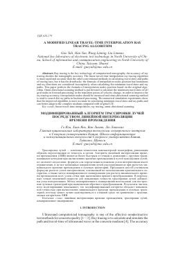
The regular grid is in Fig. 1, a ray goes through the grid boundary and arrives at the point C between A and B, this ray can come from any point of P1P2 and P3. Supposing that the slowness in this grid is s, the length between the discrete points A and B is L, the travel-time of A(xA, yA) and B(xB, yB) are TA and TB. Then the travel-time of C(xC, yC) can be calculated oy linear interpolation principle as follow:
Tc = TA (TB - TA). (1)
Supposing the point C come from P (P is the any point of P1, P2, P3), the travel-time of P can be calculated as:
tP = tc+^V"cxP™"xC)i+cyP-^yC)i=
= ta + - tA ) + , (2)
if xC = r, TB - T. = AT, according to Fermat's principle of minimum travel-time,
8T
the partial derivative of TP about r is equal to zero. That is: = 0. We can achieve:
(x - r)2 = AT2 (yr - yc )2 (3)
(xp r) L2 s2- AT2 • (3)
In most literatures, the interpolation nodes position r was calculated by Eq. (3) as:
r = xp - ATSyPL2d. (4)
P Vl2 s2- AT2
P,
A C B X
Fig. 1. The intersection diagram of grid boundary and ray.
In practice, r is calculated as follow:
AT (yp -yc)
r = Xp ±
(5)
7 L2 s2 - AT
Where, L2s2 > AT2, putting r into Eq. (2), we can achieve:
Tp = TA ^^lt1 at+(6)
Above formulas should satisfy the condition: xa < r < xb, we can derive. When xp < xa < xb, that is the Pl on the left boundary of grid,
AT (yP - y a)
r = xP +
^L2 s 2- AT2
AT should satisfy the condition:
Ls ( xa Xp )
if AT >
if AT <
Vo XA XP ) + (yA - yp )2
Ls ( xB - xP )
V (x s- xp )2 4 -(ys - y )2'
LS (XA - xp ) , t
< AT <-
Ls ( Xq Xp )
~(yB-ypf
, then, r = xb,
(7)
(8)
then r = x,.
When x < xB < x that is the P2 on the right boundary of grid,
AT (yp-yc) V L2 s2- AT2
(9)
r
r = Xp -
AT should satisfy:
Ls ( Xp Xg )
<AT <
Ls ( Xp )
V ( XP - ) + ( Jp - Ув ) ylJxP-xÂf+iyP^-yÂ)
if AT>
if AT <
Ls ( Xp Xa )
/¡^P-^Aj^+CyP-yA))
Ls ( Xp Xg )
V ( XP - XB )2 + ( jp - Ув )2
then r = X,
then r = x„ .
When xA < xp < xB, r has two values with the different range of AT, if AT satisfies:
Ls(Xp Xa)
< AT <-
Ls ( Xp Xa )
then,
r = Xp -
AT ( yp - Уа)
<Jl2 s2- AT2
if AT satisfies:
Ls ( Xg Xp )
< AT <
Ls ( Xg Xp )
then,
r = Xp +
AHyp-yc)
yjL2 s2- AT2
(10)
(11)
(12)
(13)
(14)
When xA < xp < xB and AT satisfies condition (11) and (13), r should be calculated by formula (12) and (14), then r is putted into formula (6), and two values of Tp will be achieved. The true value of r is that make the value of Tp smaller. if condition (11) and (13) are not satisfied, taking: r = xA and r = xB, then r is putted into formula (6), we select the value of r that make TP smaller.
3. IMPROVEMENT OF LTI ALGORITHM
In the forward processing of original LTI algorithm, the travel-time of nodes is calculated by scanning the ray directions which lie in the left half-plane or right half-plane column by column. The all possible ray directions aren't considered, which results in the Fermat condition of minimum travel-time was not satisfied. Aiming at this defect, this paper adopts omni-directional scanning method to calculate the minimum travel-time of all grid nodes. In backward processing, when the ray point lies on the transition boundary of velocity changing acutely or defect region, in order to improve the ray tracing accuracy, the interpolation nodes will be increased and omni-directional scanning method will be used to search for ray path.
3.1. Improved forward processing algorithm
When we calculate the minimum travel-time of nodes, we should select accurate calculating formula of r according to different cases and use formula (6) calculating the travel-time.
The steps of improved forward processing algorithm could be described as following:
(1) Calculating the travel-time of nodes using the original LTI algorithm. We can scan the nodes in the whole region from shot point 5 to the left boundary and right boundary of the region column by column. The nodes lying in the left region of shot point are scanned in four directions of 5, 6, 7, 8 as shown in Fig. 2(a) and the corresponding travel time is calculated by formula (6). The nodes lying in the right region of shot point are scanned in four directions of 1, 2, 3, 4 and the corresponding travel time is calculated. The shortest travel-time of the four directions should be the nodes travel time. The corresponding secondary source is to be recorded. If there are some interpolation nodes, the ray directions should be increased correspondingly. If the nodes lie on the region boundary, the ray directions should be decreased correspondingly.
(2) Scanning the nodes from the left boundary and the right boundary to shot point column by column. The nodes lying in the left region of shot point are scanned in four directions of 1, 2, 3, 4 and the nodes lying in the right region
Для дальнейшего прочтения статьи необходимо приобрести полный текст. Статьи высылаются в формате PDF на указанную при оплате почту. Время доставки составляет менее 10 минут. Стоимость одной статьи — 150 рублей.