^ ЭЛЕКТРОНИКА
И РАДИОТЕХНИКА
CHARACTERIZATION OF COMMERCIAL-OFF-THE-SHELF ELECTRONIC COMPONENTS AT CRYOGENIC TEMPERATURES
© 2014 n I. Valiente-Blanco", E. Diez-Jimenez*, J. A. Cervantes-Montoro*, J. L. Perez-Diaz"
aInsitituto Pedro Juan de Lastanosa, Universidad Carlos III de Madrid E28911 Madrid, Spain, e-mail: ivalient@ing.uc3m.es bDepartamento de Ingeniería Mecánica, Universidad Carlos III de Madrid E28911 Madrid, Spain, e-mail: ediez@ing.uc3m.es Received February 15, 2013; in final form, July 12, 2013
Electronic components which are able to work at cryogenic temperatures are demanded in cryogenic instruments, high sensitivity measurement systems, space missions, medical diagnosis among other applications. Different non-cryogenic commercial electronic components have been characterized between room temperature and —196°C. A simple measurement technique, taking advantage of the temperature gradient inside a partially empty LN2 Dewar vessel has been used. The results of the electrical characterization show that some of these components can be used at cryogenic temperatures with a reasonable performance even if their specifications datasheets state the contrary.
DOI: 10.7868/S0032816214010212
1. INTRODUCTION
The use of electronic components at cryogenic temperatures is a requirement increasingly demanded in cryogenic instruments, high sensitivity measurement systems, space missions, medical diagnosis where very low temperatures can be reached [1, 2]. In addition, Cryogenic Power Electronics (CPE) presents some advantages such as its increased power density, improved efficiency, noise-ratio reduction of the signal or reduced thermal degradation [3—5]. In this context, passive components like resistors, capacitors or diodes are needed for construction of more complicated electronic circuits, including motor drive electronics, analog-to-digital converters, oscillators, filters or to control the flow of power in CPE circuits [6]. Cryogenic electronics are also used in labs in order to make cryogenic motor prototypes or amplifiers [7—10].
It is difficult to find information about the behaviour of commercial electronics at cryogenic temperatures; most manufacturers just provide information about the response of their components to more standard temperatures, typically to —50...—60°C. However some of these components still can work with a reasonable performance at cryogenic temperatures, even down to 4.2 K [7, 11]. In general, for characterization of electronic components at cryogenic temperatures, expensive and complex equipment [12] is usually required, like environmental chambers or cryostats [10, 13-16].
Taking advantage of the thermal gradient inside a partially empty LN2 vessel, we have characterized electronic commercial components such as commercial resistors, capacitors and diodes over a range of temper-
atures between room temperature and LN2 temperature (—196°C). This technique allows a fast testing procedure along a wide temperature range with a small dimension, simple cryogenic equipment and low cost which turns out to be a very desirable aspect [17-19]. The behaviour of different commercial-off-the-shelf electronic components has been characterized using this technique between +20°C and -196°C. Finally, resistors, capacitors, diodes and different PT-100 sensors have been tested and their behaviour characterized with respect to their temperature.
2. EXPERIMENTAL SET UP AND PROCEDURE
The experimental set up is shown in Fig. 1. The experimental test facility is mainly composed of a LN2 Dewar with a 32-litre capacity from MVE cryogenics
(1) which is which is partially filled with liquid nitrogen (LN2). The level of LN2 was always controlled and fixed at about 24 cm from the bottom. The experimental set up also includes a hand-controlled XZ table for the positioning of the components inside the cryostat
(2) fixed to an optic table that assures good flatness (3), and an extension holder made of a non-thermal conductive material (4) for the printed circuit that contains the electronic components (5). The printed circuit carries four sockets so the electronic components can be swapped in and out fast and easily. Low supply currents assure little thermal and electromagnetic interference between the components.
In order to measure the capacitance of the capacitors and the forward voltage in the diodes, a multimeter (ICE MD5600) has been used. Voltage and current are measured and generated by independent channels
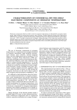
Temperature, °C 0
-40- /
-80- / -120- J
-160- / -200
0 80 160 240 320
Distance to LN2 surface, mm
Fig. 2. Temperature vs. distance to the LN2 surface in the Dewar vessel.
different components in the printed circuit. All resistors and PT-100 sensors have been characterized in a four-wire connection to avoid errors in measurement introduced by the connection wires between the electronic components and the acquisition system. Each of the PT-100 sensors is calibrated using a "three points" calibration procedure measuring their resistance at +25, 0 and -196 ± 0.1°C. Current and voltage are measured with the NI-6008 data acquisition board.
in a NI-6008 data acquisition and generation card. When the electronic components get closer to the PT-100 sensors, according to DIN IEC 751, have LN2 inside the Dewar vessel, their temperature drop. been used in order to measure the temperature of the This way, the behaviour of the tested commercial com-
Fig. 1. Experimental set up: (1) dewar vessel; (2) XZpositioning table; (3) optic table; (4) wood extension holder; (5) printed circuit with the electronic components.
Normalized resistance, p.u. 2.0
Carbon film
Metal film Cu_Pb
Solic ceramic
Holco
Thin metal film Ni_Cr
Wirewound vitreous
Metal glazed
Wirewound ceramic
-120 -80 -40 Temperature, °C
Fig. 3. Normalized resistance vs. temperature of all resistors in Table 1; f = 0 Hz.
Table 1. Resistors studied in the experiments
Legend Description Resistance Power disipa-tion, W Temperature coefficient, ppm ■ K-1 Manufacturer Reference Data sheet minimum temperature, °C
Carbon film Carbon film resistor 100 Q 0.5 >-450 TE connectivity CFR50J100R -55
with alumina core
Metal film Metal film Cu-lead- 47 kQ 2 <200 Vishay PR02000204702JA100 -55
Cu_Pb ed resitor
Ceramic Ceramic composi- 10 Q 0.5 +300 ... -900 TE connectivity CCR210RKB -40
film tion resistor
Matal Metal glaze leaded 1 MQ 1 <200 TE connectivity VR68000001004JAC00 -55
glazed film resistor
Wirewound Ceramic body wire- 1 Q 7 ±400 TE connectivity SBCHE61R0K 0
ceramic wound resistor
Holco Metal film Holco 100 Q 0.25 ±15 TE connectivity H8100RBYA -55
series
Wirewound Copper clad steel 10 Q 7 ±75 Welwyn compo- W22-10RJI -55
vitreous wire and vitreous nents
enamel coating
Thin metal Metal film tinned 1 MQ 0.6 ±100 TE connectivity LR1F1M0 -55
film Ni_Cr copper leaded wires
Table 2. Capacitors studied in the experiments
Legend Description Capacitance Manufacturer Reference Data sheet minimum temperature, °C Loss of 90% capacitance, °C
Paper Impregnated metallized 47 nF Evox-Rifa PME271E547M -40 -
paper
Elect. Al Aluminium electrolitic 100 ^F Yageo SK016M0100B2F-0511 -40 -25
Ceramic Ceramic capcitor class 1 nF Murata DE2E3KH102MN3A -25 -140
X1/Y1
PET film Metallized PET film 10 nF Epcos B32529C1103J -55 -
capacitor
Solid Tanta- Solid tantalum capacitor 220 nF Vishay 489D224X0035A6VE3 -55 -
lum
Mica Mica capacitor 100 pF Cornell-Dubilier CD15FD101JO3F -55 -
ponents can be characterized with regard to their temperature. Besides this measurement, the components have been characterized with respect to thermal cycling, i.e., measured again after warming up to room temperature.
When the electronic components are outside the Dewar vessel, they are at room temperature and at a certain distance from the surface of the LN2. As the Z position is modified and the distance to the liquid nitrogen reduced (see Fig. 2), the temperature of the electronic components is decreased. Temperature vs. distance to LN2 surface is plotted in Fig. 2.
3. RESULTS AND DISCUSSION
Different commercial electronic components have been characterized over a range of temperatures between ambient temperature and — 196°C. According their specifications all tested components have typical minimum operating temperatures of—50...—60°C. The results of our experiments are introduced and discussed in the following sections.
3.1. Resistors
An initial series of tests has been carried out with different resistors like thin film, power wirewound,
Normalized resistance, p.u. 1.10
Temperature, °C
Wirewound vitreous
Carbon film
Fig. 4. Normalized resistance vs. temperature of some of the resistors measured; f = 0 Hz.
metal film or carbon composition resistors, measuring the change in their resistance at temperatures from +20 to —196°C. All the resistors characterized in this section are summarized in Table 1.
Normalized resistance with respect to room temperature resistance vs. temperature for all the resistors in Table 1 is shown in Fig. 3. Two of the resistors reveal great variations in resistance with temperature. The ceramic wirewound resistor initially decreased its resistance, reaching a minimum at around —80°C with a drop in its resistance of about 50%, and then increases more than 100% with respect to its room temperature value at about —180°C. The resistance of the solid ceramic resistor increases gradually to a maximum of about 20% at -190°C.
The resistance of carbon film and metal glazed resistors increases by ~6% at —196°C. A Holco series resistor presented an outstanding performance, with a maximum variation of 0.5% over all the measured range of temperatures. The resistance of the rest of the resistors in Fig. 4 decreased between 1% and 3% at—196°C.
After thermal cycling, the resistance has been measured again at room temperature. Two different resistors of
Для дальнейшего прочтения статьи необходимо приобрести полный текст. Статьи высылаются в формате PDF на указанную при оплате почту. Время доставки составляет менее 10 минут. Стоимость одной статьи — 150 рублей.