ЛАБОРАТОРНАЯ ТЕХНИКА
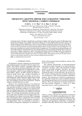
FREQUENCY ADAPTIVE DRIVER FOR ULTRASONIC VIBRATORS WITH MOTIONAL CURRENT FEEDBACK © 2013 t. C.-C. Wen",b, F.-L. Wenc, C.-H. Linb
aDepartment of Electronics Engineering, Ta Hwa of Institute Technology, Hsinchu County 307, Taiwan bDepartment of Electrical Engineering, Tatung University, Taipei City 104, Taiwan cDepartment of Mechanical & Computer-Aided Engineering/Graduate Institute of Automation & Mechatronics, St. John's University/Taipei Campus, Tamsui District, New Taipei City 25135, Taiwan E-mail: ericwen@mail.sju.edu.tw Received February 1, 2012
A driving circuit of frequency adapting for an ultrasonic vibrator with motional current feedback has been presented in this paper. Via a voltage-controlled oscillator (VCO) and a digital/analog converter (DAC), the driving signal would be magnified by a linear power amplifier to actuate the vibrator. Since the vibrating velocities or displacements at the surface end of a vibrator could be predicted through the measurement of motional current, the motional current passing through the vibrator was detected by a current transformer (CT) type sensor as feedback to monitor the optimal level of output power. The calculation for phase difference and the tuning strategy for driving frequency were implemented by a microcontroller integrated with an A/D converter and a voltage comparator as well as the signal attenuation and level tuning circuit. The experiment demonstrates that the temperature effect corresponding to frequencies is at 9.75 Hz/°C shifting and the external loading reflected to frequencies is about 8.3 Hz/gm offset. The proposed circuit has the great performance in rejecting the disturbances from external loading and thermal effect.
DOI: 10.7868/S0032816213010138
1. INTRODUCTION
An ultrasonic vibrator comprises two piezoelectric rings abutting against each other with two copper electrodes. This vibrator could be assembled with metal horns to gain larger vibrating amplitudes and to produce the specific deflection in longitudinal or transverse direction, called as a bolt-clamped Langevin vibrator (BLT). Hence, the BLT vibrator has high mechanical quality factor (Qm: detailed description in equation 3), high strength and solidity, and low thermal dissipation. Major ultrasonic applications of high powers include cleaners, plastic welding, cutting, sewing, wire bonding, precious stone perforators, medical scalpels, and fish detectors or sonar.
However, the actuating frequency of an ultrasonic BLT vibrator is usually near resonance based on various equivalent models [1], but it is not constant. Being influenced by operating conditions on external loadings or working temperatures, the optimal frequencies have the shifting phenomena [2] resulting in resonant failure. To overcome the drawback, several servo driving circuits and controllers were developed with voltage feedback [3] or phase-lock-loop (PLL) technique [4]. Unfortunately, these complicated drive faced the difficult implementation for the purpose of commercial applications. Thus, we would like to introduce a novel driver of frequency adapting for an ultrasonic vi-
brator with motional current feedback, instead of the previous servo drive.
The optimal characteristic of electromechanical conversion is nearby resonance fr for most kind of piezoelectric ceramics, where the maximum working current is obviously obtained. Therefore, the maximum output power is also generated at electromechanical resonance. In the past issues, the electric feature nearby resonant and anti-resonant frequencies was measured by a HP 4194A gain/phase impedance analyzer. The parameters of electrical components in the equivalent circuit were used to estimate dynamic electromechanical behaviors of a vibrator in frequency domain. Then, the equations of resonant frequency fr and anti-resonant frequency fa, based on a static equivalent circuit, could be expressed as [5]:
f r =
1
f a =■
2W LmCm 1
(1)
(2)
2W LmCmC0 /(Cm + C0)
where Cm and Lm represent the equivalent mechanical compliance (1/k) and the equivalent mass of a vibrator, respectively, and C0 represents the damped capacitance. Also, k stands for the stiffness of a vibrator. The minimum and maximum magnitudes of impedance modulus of the BLT vibrator occur at the resonant fre-
1
0_ №rLm __
m r R C
Rm RmCm
(3)
ating at high voltage or power could be computed as equation (4),
A = •
№rV 0
(4)
Fig. 1. Dynamic equivalent circuit of a vibrator [6].
quency and the anti-resonant frequency, respectively; i.e., in the point of energy view, maximum and minimum power output of the BLT vibrator is excited at the resonant frequency and the anti-resonant frequency, individually. Therefore, the function of quality factor Qm is the ratio of electromechanical transformation and inversely proportional to internal energy loss Rm, calculated as
where ®r is the angular frequency of a vibrator at resonance, v0 is the amplitude of mechanical vibration of an vibrator. After calculating the force factor, the equivalent parameters measured from an impedance analyzer can be converted into the practical operating parameters of the mechanical side via equation (5):
Rm A 2
Lmech Lm A
C
C„
mech
(5a) (5b)
(5c)
where ®r is the angular frequency of a vibrator at resonance. Here, it is ®r = 2nf (rad/sec). The resistance Rm represents the lump-sum loss of the mechanical damping and the dielectric loss. Furthermore, parameters of equivalent circuit, including Rm, Lm, Cm, C0,f and fa, are measured at a low voltage (l Vrms) using a HP4194A impedance analyzer, and thus Qm calculated by equation (3). Through the measurement of electrical feature, the vibrating amplitude and phase of BLT vibrators could be predicted based upon the parameter value of electrical components in an equivalent circuit. It was also applied to pre-determine the performance of BLT vibrators. Normally, resonant frequency fr is major operating frequency for ultrasonic actuating systems. Equivalent circuits are usually simulated and experimented through electrical components for the design purpose of a driving circuit and control to an ultrasonic BLT vibrator.
Moreover, the dynamic equivalent circuit [6] could be constructed based on the motional current and micro vibration measurement through optical fiber [2], as shown in Fig. 1, where A represents the force factor, Im denotes the motional current which is an excellent sensing target [7—9], and V is vibrating velocity of an vibrator. The electrical parameters of C0 and R0 represent dielectric loss and electrical energy loss in the electrical side, respectively. Also, Rm, Lm, and Cm are included in the mechanical side. Applying the measuring results of motional currents and micro-vibration, after also the calculation of the force factor A, the output power and efficiency in the mechanical side (right hand side) could be derived from the electrical side (left hand side) [10].
Thus, we expected that the mechanical output power is the multiplication of vibrating velocities and ended forces. Therefore, employing the measurement system to obtain the motional currents Im and mechanical vibrating amplitude, the force factor A oper-
where Rmech, Lmech, and Cmech are counted into the bulk effect of force factor A as the real mechanical output for a vibrator.
When the input driving frequency is closer to the resonant frequency of a vibrator, the only Rm is left, due to the resonance, in the mechanical side of the equivalent circuit. Thus, through the calculation found in equation (6), the output force F of a vibrator could be [11]
Fo = VA. (6)
The direct and converse piezoelectric effect of an ultrasonic vibrator should be considered as energy conversion for a frequency drive with adapting function in this study, where an ultrasonic vibrator is the perturbation source to generate ultrasonic vibration. Based upon the detection of motional current where there is phase difference compared to driving voltages, the frequency adaptive drive is implemented and evaluated through experimental performance of external loading disturbances and working temperature interferences.
2. EXAMPLES OF ELECTROMECHANICAL
COUPLING DESCRIBED BY MOTIONAL CURRENT
In practical applications, the ultrasonic vibrator is usually operated at 30 Vpp as a high power actuator. Therefore, there are different features exhibited in the HP analyzer measurement. For the characteristic evaluation and control purpose, the vibrating velocity and motional current are used as the feedback for a vibrator drive. By performing the integration of the vibrating velocity with time, the vibrating displacement could be obtained, which was compared to micro-vibration measurement through optical fiber detection.
Since the detection of motional currents is much easier than that of vibrating velocities, the motional current became the major measured parameter. Based on the equivalent circuit, the motional current Im (that is, the current passing Cm—Rm—Lm components) is proportional to the vibrating velocity of a vibrator. Al-
m
2
Motional current, A 2.5
2.0
1.5
1.0
0.5
0
Resonant
: shifting * 15 V
25 V
1 Wi i - 35 V
-.:- 45 V
Vin = 45V.. ^ T * * i v ..
Vm = 15 V 1 1
39.0 39.5 40.0 40.5 41.0
Frequency, kHz
Motional current, A 2.0
39.2
39.6 40.0 40.4 Frequency, kHz
Fig. 2. Shifting phenomena of resonant frequencies based on motional current detection for a BLT vibrator.
Fig. 3. Hysteresis loop of an ultrasonic vibrator.
so, the vibrating velocity was multiplied by end force to calculate the mechanical output powers of a vibrator. Thus, the vibrating velocities and displacements at the end of a vibrator can be predicted through the measurement of motional currents.
With high voltage input, the resonant frequency is shifted for a vibrator. The input voltage has a great effect on the resonant frequency as shown in Fig. 2. The resonant frequency is 39.9 kHz and 39.7 kHz driven at
Для дальнейшего прочтения статьи необходимо приобрести полный текст. Статьи высылаются в формате PDF на указанную при оплате почту. Время доставки составляет менее 10 минут. Стоимость одной статьи — 150 рублей.