MODELING OF THE DRIVE SYSTEM POWERED BY THE PV-ARRAY FOR WATER PUMPING*
G.E. Ayvazyan, G. H. Kirakosyan, K.M. Melkonyan, A.H. Vardanyan
«Viasphere Technopark» Co. 41, Arshakunyats St., Yerevan, 375025, Armenia Fax: (+374-1)44-09-31; e-mail: agag@arminco.com
The behavior and performances of the PV pumping drive system are investigated under the envi- ^ ronment of MATLAB/SIMULINK. The good adaptation of the load power to the maximum power § delivered by the PV array is obtained. On the basis of the simulink-model and new strategy commands ^ the modeling of the drive system is performed.
e
Solar energy can be directly converted into DC electricity by using photovoltaic (PV) technology, which in turn can be used for pumping water. There are four main markets for PV-powered water pumping systems with a growing variety of applications serving people around the world: village water supply, spray irrigation, livestock watering and residential needs [1-4].
The PV water pumping system consists of PV array, MOSFET based inverter, DC motor coupled to a pump and a controller. In small units of about 0.3 kW to 5.0 kW, permanent magnet brushless (PMB) DC motors are preferable because of their higher operating efficiency and good starting torque [5]. In this arrangement, the PV array directly converts the light intensity into a DC current which then is fed to the PMB DC motor through a MOSFET based inverter. These motors can successfully pump the water even though there is a variation in the input DC voltage due to the variation of solar radiation. In such systems the performance of each unit both under steady-state and during starting depends not only on the type of the motor and the pump characteristics, but also on the relative size of the unit and PV array.
The aim of this article is the modeling of the drive system which includes the PV array, reference current generator, hysteresis current controller, inverter and permanent magnet brushless DC motor. The operation of PV array near the maximum power point is realized through the closed loop operation of the drive. The reference current generator generates the reference currents by using the reference torque (T*) and rotor position (0r). The hysteresis controller contributes the switching pattern to the inverter. The study also examines the effectiveness of the drive system both for starting and DC link voltage variations caused by varying the light intensity.
1. Modeling of the drive system
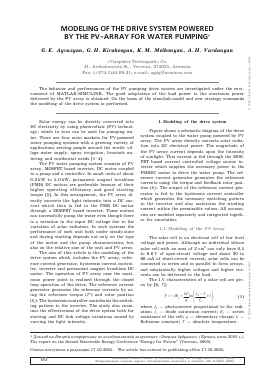
Figure shows a schematic diagram of the drive system coupled to the water pump powered by PV array. The PV array directly converts solar radiation into DC electrical power. The magnitude of the PV array current depends upon the intensity of sunlight. This current is fed through the MOS-FET based current controlled voltage source inverter which supplies the necessary power to the PMBDC motor to drive the water pump. The reference current generator generates the reference currents using the torque and feedback rotor position (0r). The output of the reference current generator is fed to the hysteresis current controller which generates the necessary switching pattern to the inverter and also maintains the winding current within the permissible values. All accessories are modeled separately and integrated together for simulation.
1.1. Modeling of the PV-Array
The solar cell is an electrical cell of low level voltage and power. Although an individual silicon solar cell with an area of 2 cm2 can only have 0.5 to 0.6 V of open-circuit voltage and about 30 to 60 mA of short-circuit current, solar cells can be connected in series and in parallel to form arrays, and substantially higher voltages and higher currents can be delivered to the load.
The I-V characteristics of a solar cell are given by [6, 7]:
V = - IRs +-
T q
ln
Il -1
-+1
(1)
where IL — photocurrent proportional to the radiation; Is — diode saturation current; Rs — series resistance of the cell; q — elementary charge; k — Boltzman constant; T — absolute temperature.
* Доклад на Второй конференции по возобновляемой энергетике «Энергия будущего» (Ереван, июнь 2005 г.). The report on the Second Renewable Energy Conference "Energy for Future" (Yerevan, 2005)
Статья поступила в редакцию 17.10.2005. The article has entered in publishing office 17.10.2005.
Of) International Scientific Journal for Alternative Energy and Ecology ISJAEE №12(32) (2005)
Ow Международный научный журнал «Альтернативная энергетика и экология» АЭЭ №12(32) (2005)
Г. Е. Айвазян, Г. Н. Киракосян, К. М. Мелконын, А. Н. Варданян
Моделирование системы привода водяного насоса, управляемой с помощью панели солнечных батарей
Solar PV-array MOSFET based VSI
: vdc
i = -(ib + i ) abc
References a Hysteresis
.. * ib
current current
generator iL ' c , controller
Position to speed converter
Block diagram of the drive system
The equation of the solar generator which consists of Ns number of cells in series and Np cells in
s p
parallel is given by:
Vg =-IgRsNs/Np + + (NskT/q)lnf1 + (( -Ig/NpIs) =
l/ Dgj ln (1 + (
= -IsRsg +1
( -Ig V0g)
(2)
and I0 g = NpIs.
where RSg = RSNS/Np , Dg = q/kTNs
The motor, which is used in this analysis is rated at 34 V and 90 A. Therefore, a suitable solar generator of the given solar cell type consists of 30 panels in parallel and each panel consists of 60 cells in series.
1.2. Modelling of the motor and an inverter
The general volt-ampere equations of the PMB DC motor drive can be expressed as [5, 7]:
= Ri + d ^a =
+ ea
П- d Xb
vbn = Rib +—TT + ebn dt
n- d Xc
= R'c + ~t
+ e„
(З)
(4)
(б)
where v , vb and v
an bn cn
be determined as:
are phase voltages and may
^ = va0 - vn0 ' vbn = vb0 - v
vb0 ■
where v
a0'
b0;
vc0 and vn0
n0' vcn = vc0 - vn0, (6)
are three phase and
neutral voltages referred to the zero reference potential at midpoint of DC link. R is the resistance per phase of the stator winding, ean, ebn and ecn are phase to neutral back emfs, Xa, Xb and Xc are total flux linkages of phase winding a, b and c, respectively. These values can be expressed as:
Xa = Ls'a -M (b + 'c) (7)
Xb = Ls'b - M (a + 'c ) (8)
Xc = Ls'c - M (a + 'b ) (9)
where L and M are the self and mutual inductances respectively, and ia, ib and ic are the actual winding currents of a, b and c phases.
The PMB DC motor has no neutral connection and hence it leads to:
ia + 'b + ic = 0. (10)
By substituting Eqs. (7)-(10) in Eqs. (3), (4) and (5), the volt-ampere equations result in the state space current derivative form:
da dt
- = 1/(Ls + M)(an - iaR - ean V (11)
di dt
b- = 1/ (Ls + M )(bn - ibR - ebn V
(12)
die dt
= + M) (cn - 'cR - ecn )• (1З)
- = (P/2)(Te - T1 - BP) J,
(1б)
The developed electromagnetic torque may be expressed as:
Te = (ean'a + ebn'b + ecn'c )) = ( 1 4 )
where Q is the rotor speed in electrical rad/s.
The mechanical equation of the motion in speed derivative form can be expressed as:
d Q dt
where T1 is the load torque in Nm which is modeled for pump load, B is the frictional coefficient in Nms/ rad; J is the moment of inertia of the shaft in Kg-m2; and P is the number of poles of the motor.
The expression of torque runs in to computational difficulty at zero speed, as the induced emfs are zero. The three phase back emf for PMB DC is in trapezoidal shape. For this purpose, the back emfs are expressed as the function of rotor position (9r) as:
ean = kbfa (9r )Q, (16)
ebn = kbfb (9r)Q, (17)
ecn = kbfc (9r )Q, (18)
where fa (9r), f (9r) and fc (9r) are functions of rotor position. Substituting Eqs. (16), (17) and (18) in Eq. (14) gives the torque expression as:
Te = Kb [ fa (9r )ia + fb (9r )'b + fc (9r )ic]. (19)
Also the derivative of rotor position 9r in state space form is given by
d9r
dt
- = P.
(2G)
The trapezoidal back emf is not balanced and the applied voltage at time may be unbalanced, depending on the switching state of the inverter. The potential of the neutral point with respect to the reference zero potential (vn0) is obtained by substituting Eq. (6) in (3), (4) and (5) and rearranging, it gives:
(21)
n0
= [l
a0 '
vb0 ■
"c0
-(e
Kbn -
OV 3.
1.3. Reference current generator and hysteresis current controller modeling
The input signals to the reference current generator are reference torque and the function of
International Scientific Journal for Alternative Energy and Ecology ISJAEE № 12(32) (2005) Международный научный журнал «Альтернативная энергетика и экология» АЭЭ № 12(32) (2005)
S1
r
w
9
Солнечная энергетика
back emf. The magnitude of the three phases current (I*) is determined by using reference torque (T*) and the back emf constant Kb as:
I * = T */Kb.
Depending upon the rotor position, the reference current generator creates the reference currents (i*a, i* and ic) by taking the value of reference current magnitude as I*, -I* and zero. The values of reference currents are modeled for every 60° [7].
The reference current generator creates the three phase reference currents by using the reference torque and rotor position. Position to speed converter allows organizing a feedback by the torque. Actually the reference currents are generated to be compared in the hysteresis current controller. The comparison result is applied to the input of MOSFET based inverter by means of which the switching algorithm of the 3 phase PMB DC Motor voltage is generated.
The feedback balance equation has the following form
t *(er ) = f ( + w).
The hysteresis current controller output value variation interval depends on the flexibility of the motor mechanical characteristic.
In the present system, the hysteresis current controller contributes the switching pattern and switching logic to the inverter devices [7].
2. Simulation and result discussion
We have obtained the set of dynamic equations (2), (11), (12), (13), (15), (19) and (20) of the system, which allow us to analyze the performance of the drive system. The above
Для дальнейшего прочтения статьи необходимо приобрести полный текст. Статьи высылаются в формате PDF на указанную при оплате почту. Время доставки составляет менее 10 минут. Стоимость одной статьи — 150 рублей.