УДК 620.179
RESIDUAL STRESS EVALUATION IN DISSIMILAR WELDED JOINTS USING FINITE ELEMENT SIMULATION AND THE Lcr ULTRASONIC WAVE
Yashar Javadi, Mehdi Ahmadi Najafabadi1, Mehdi Akhlaghi Department of Mechanical Engineering, Amirkabir University of Technology,
424 Hafez Ave, Tehran,Iran
Abstract. Subsurface stresses in welded structures increase the likelihood of fatigue cracks and environmental induced material degradation. The ability to evaluate stresses at the surface as well as in the interior of welded structural members would substantially increase the accuracy of structure life estimation. The longitudinal critically refracted (LCR) wave is a bulk longitudinal mode that travels within an effective depth underneath the surface. It may be used to detect in-plane subsurface stresses in the structures. This paper presents a three dimensional thermo-mechanical analysis to evaluate welding residual stresses in dissimilar plate-plate joint of AISI stainless steel 304 and Carbon Steel A106-B type. After finite element simulation, the residual stresses were evaluated by Lcr ultrasonic waves. Finally the results of two methods were compared and verified by holedrilling method. This paper introduces a combination of "Finite Element Welding Simulation" and "Ultrasonic Stress Measurement using the LCR Wave" which is called as "FELCR". The capabilities of FELcr". The capabilities of FELCR in residual stress measurement are confirmed here. And also this paper evaluates residual stresses of dissimilar welded joints by LCR ultrasonic waves. It has been shown that predicted residual stress from three dimensional FE analyses is in reasonable agreement with measured residual stress from LCRmethod and also the results of both are verified with hole-drilling experimental measurements.
Keywords: Finite Element Welding Simulation; Ultrasonic Stress Measurement; Acoustoelastic Effect; Welding Residual Stress; LCR; FELCR; Hole-Drilling Measurement; Dissimilar Welded Joint.
ОЦЕНКА ОСТАТОЧНЫХ НАПРЯЖЕНИЙ В СВАРНЫХ СОЕДИНЕНИЯХ ИЗ РАЗНОРОДНЫХ КОМПОНЕНТ С ИСПОЛЬЗОВАНИЕМ МОДЕЛИРОВАНИЯ МЕТОДОМ КОНЕЧНЫХ ЭЛЕМЕНТОВ И ИЗМЕРЕНИЯ ГОЛОВНОЙ УЛЬТРАЗВУКОВОЙ ВОЛНОЙ
Яшар Джавади, Мехди Ахмади Наджафабади, Мехди Ахлаги Отдел механической техники, Технологический университет Амиркабир, 424 ул. Хафеза, Тегеран,
Иран
Подповерхностные напряжения в сварных соединениях увеличивают вероятность возникновения усталостных трещин и деградации материала. Способность оценивать напряжения как на поверхности, так и внутри объектов со сварными соединениями существенно повышает точность оценки срока эксплуатации. Продольная волна, преломленная под критическим углом (Ьск) — это объемная продольная волна, которая распространяется в пределах эффективной глубины под поверхностью (головная волна). Она может быть использована для того, чтобы детектировать подповерхностные напряжения в сварных соединениях, ориентировнные в плоскости поверхности. В работе представлен трехмерный термомеханический анализ оценки остаточных напряжений в стыковых швах из нержавеющей стали 304 и углеродистой стали А106-В. После выполнения модлирования остаточные напряжения были оценены у. з. волнами. Окончательно результаты этих двух методов сравнивали между собой, а также проверяли методом сверления. Вводится комбинация "Моделирования сварных швов методом конечных элементов" и "Ультра-
1 Corresponding author, Tel.: +98 21 6454 3431; fax: +98 21 66419736 E-mail addresses: ahmadin@aut.ac.ir (M. Ahmadi Najafabadi)
звукового измерения напряжений с использованием волны ЬСЕ", которая названа РЕЬСК. Возможности измерений остаточных напряжений с использованием РЕЬСК подтверждены в статье. Показано, что предсказанные трехмерным методом конечных элементов остаточные напряжения находятся в разумном согласии с измеренными методом ЬСК и все эти результаты подтверждены методом сверления.
Ключевые слова: расчет сварных соединений методом конечных элементов, у. з. измерение напряжений, акустоупругий эффект, остаточные напряжения сварных соединений, ЬСК, ЕЕЬСК, измерение напряжений сверлением, сварные соединения разнородных элементов.
1. INTRODUCTION
Residual stresses are present in materials without any external pressure, and generally result from deformation heterogeneities appearing in the material [1]. They play an important role in the strength and service life of structures. Welding is an assembly process often used in the mechanical industries, especially in the pressure vessel industry. According to the process and temperatures reached during this operation, harmful thermo-mechanical stresses may appear in the welded joint. To optimize the structures' design and control their mechanical strength in service, it is very important to determine the residual stress levels with a non-destructive method. The high industry request for the stress evaluation techniques encouraged development of several methods like X-ray diffraction, incremental hole drilling, and more recently the ultrasonic waves and the Barkhausen noise methods. Many studies clearly showed that there is no universal or absolute method that gives complete satisfaction in the in-situ non-destructive stress monitoring of the mechanical components. Many parameters such as material, geometry, surface quality, cost, and accuracy of the measurement, etc., must be taken into account in choosing an adequate method.
1.1. Ultrasonic method
The ultrasonic method was chosen for stress measurement because it is non-destructive, easy to use, and relatively inexpensive. However, it is rather sensitive to the microstructure effects (grains size [2—4], carbon rate [5, 6], texture [7—10], and structure [11—13]) and to the operating conditions (temperature [14, 15], coupling [16, 17], etc.). The ultrasonic evaluation of the residual stresses requires separation between the microstructure and the acous-toelastic effects.
1.2. Welding Simulation
The extent of deformations and residual stresses in welded components depends on several factors such as geometrical size, welding parameters, welding sequence and applied structural boundary conditions. Finite element (FE) simulation has become a popular tool for the prediction of welding distortions and residual stresses. Earlier studies of welding accounted for the non-linearities due to temperature dependent material properties and plastic deformations [18— 20]. The majority of those analyses were limited to two-dimensions on the plane perpendicular to the welding direction. Good correlations have been observed between the numerical predictions and experimental results [21—24].
2. THEORETICAL BACKGROUND 2.1. Acoustoelastic Effect
Within the elastic limit, the ultrasonic stress evaluating method relies on a linear relationship between the stress and the velocity or the travel time
4 Дефектоскопия, < 9, 2012
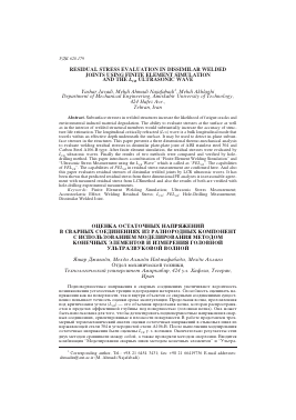
change, i.e. the acoustoelastic effect [25, 26]. The LCR method uses a special longitudinal bulk wave mode, as shown in Fig. 1, which travels parallel to the surface, particularly propagating beneath the surface at a certain depth. The Lcr waves are also called surface skimming longitudinal waves (SSLW) by
28° , TN Pie zoelectric lement PMMA Wedge C
j Steel 34° \ -J Wave % 90° Shear Wave
Fig. 1. Lcr probe for PMMA (plexiglas) wedge on steel [31].
other authors. Brekhovskii [27], Basatskaya and Ermolov [28], Junghans and Bray [29], Langenberg et al. [30] had some detailed discussions on the characteristics of the critically refracted waves. Ultrasonic stress measurement
Fig. 2. Velocity of plane wave and stress field in orthogonal directions [31].
techniques are based on the relationship of wave speed in various directions with stress. Fig. 2 shows elements of a bar under tension where the wave propagates in three perpendicular directions.
The first index in the velocities represents the propagation direction for the wave and the second represents the direction of the movement of the particles. In Fig. 2a the wave propagates parallel to the load and Vn represents the velocity of the particles in the same direction (longitudinal wave), meanwhile V12 and V13 represents the velocity in a perpendicular plane (shear waves).
In Fig. 2b and c the waves propagating in the other directions and the velocities symbols are also shown. The V22 velocity is for longitudinal waves propagating perpendicular to the stress field. The sensitivity of these waves to the strain has been established by Egle and Bray [25] in tensile and compressive load tests for a bar of pearlitic (rail) steel. The waves with particle motion in the direction of the stress fields showed the greatest sensitivity to stress, and those with particle motions perpendicular to the stress field showed the least. The most significant variation in travel time with the strain was found for longitudinal waves, followed by the shear waves when the particles vibrate in the direction of the load. The other waves do not show significant sensitivity to the deformation. The speeds of the longitudinal plane waves traveling parallel to load can be related to the strain (a) by the following expressions:
p0V12 = X + 2m + (2l + X)0 + (4m + 4X + 10^)a1, (1)
where o is the initial density; V11 is the velocity of waves in the direction 1 with particle displacement in the direction 1; X, m the second order elastic constants (Lame's constants) l, m, n are the third order elastic constants; 0 = a1 + a2 + a3 which a1, a2 and a3 are components of the homogeneous triaxial principal strains. For a state of uniaxial stress, a1 = e, a2 = a3 = -u x e, where e is the strain in the direction 1 and u is the Poisson's ratio. Using these values, Eq. (1) becomes:
p0V12 = X + 2m + [4(X + 2m) + 2(m + 2m) + vm (1+ --)]•£. (2)
M
The relative sensitivity is the variation of the velocity with the strain and can be calculated by Eq. (3). In this equation, L11 is the dimensionless acoustoelastic constant for LCR waves.
dVu/ Vu = 2 + (m + 2 m) + VM(l + 2l/X) = (3)
de X + 2m
Для дальнейшего прочтения статьи необходимо приобрести полный текст. Статьи высылаются в формате PDF на указанную при оплате почту. Время доставки составляет менее 10 минут. Стоимость одной статьи — 150 рублей.