ОПТИКА И СПЕКТРОСКОПИЯ, 2014, том 117, № 1, с. 166-173
ГЕОМЕТРИЧЕСКАЯ И ПРИКЛАДНАЯ ОПТИКА
УДК 535.312
CALCULATION OF THE LIGHT INTENSITY DISTRIBUTION REFLECTED BY A SPHERICAL CUBE CORNER RETROREFLECTOR ARRAY
© 2014 г. T. Wang, W. Wang, D. Geng, P. Du, and M. Gong
State Key Laboratory of Tribology, Center for Photonics and Electronics, Department of Precision Instruments,
Tsinghua University, 100084 Beijing, China E-mail: gongml@mail.tsinghua.edu.cn Received July 6, 2013; in final form, December 27, 2013
Because the light intensity distribution (LID) reflected by a spherical cube corner retroreflector array (SCCRA) is of great significance for the detection of the remote laser ranging to receive laser pulse echo precisely and to accomplish the function outstandingly, it is vital to find a method to calculate the LID reflected by SCCRAs with different structural parameters for the SCCRA design. Besides, considering that the reflected light goes through a complex optical system (COS) described by ABCD matrix before it reaches the detector, the method to calculate the LID should be suitable for the COS. This article derives formulae to calculate LID reflected by a SCCRA based on the lens-system diffraction formula of S.A. Collins. In the process of deriving, coordinate transformation matrixes and vector formulations are applied and the dihedral offsets are taken into account. Because the structural parameters of the SCCRA and the expression of the ABCD matrix of the COS are not limited in the deriving process, these formulae are suitable for calculation of the LID reflected by different SCCRA and going through different COS. In addition, computer simulations are applied to explain clearly how to get the LID of a SCCRA by the formulae derived in this paper.
DOI: 10.7868/S0030403414070265
1. INTRODUCTION
A cube corner retroreflector (CCR) consists of three plane mirrors placed at an angle of 90° with respect to one another [1—3]. A spherical CCR array (SCCRA) is defined as a kind of arrangement of CCRs. The CCRs are assembled in the same sphere. In addition to the geometrical optical property of the beam reflecting upon itself [4—6], the SCCRA has larger field of view than a single CCR. It is more suitable to be used for the remote laser ranging (RLR) as a cooperative target. A lot of satellites are spherical and contain many CCRs distributed over their surface for RLR. For example, AJISAI is equipped with 1436 CCRs. LAGEOS-1 and LAGEOS-2 are both equipped with 426 CCRs. ETALON is equipped with 2146 CCRs, Stella and Starlette are equipped with 60 CCRs [7]. Besides, the spherical cap shape is applied in some satellites for RLR. Such as STSAT-2B and CryoSat, STSAT-2B is equipped with 9 CCRs [8] and CryoSat is equipped with 7 CCRs [9].
As a cooperative target, the SCCRA directionally reflects the laser pulse coming from the observing station. Meanwhile, the light intensity distribution (LID) is modified by the SCCRA. The LID is of great significance for the detection of RLR to receive laser pulse echo precisely and to accomplish the function outstandingly.
Previous researches focus on the far-field diffraction of a specific SCCRA in free space [10, 11]. The results derived in them can not be applied for other
SCCRAs directly. In addition, they are only suitable for analyzing the LID of light propagating in the vacuum, but not suitable for calculating the LID of the light through other optical systems. The space from the SCCRA to the receiving detector is usually a complex optical system (COS) instead of a free space. The COS is made of the atmosphere and the optical system equipped in front of the detector. So, the LID calculated by previous researchers must be different with the real situation. Considering that both the atmosphere and the equipped optical system can be expressed by ABCD matrix [12], and the lens-system diffraction formula of S.A. Collins is suitable for analyzing the light propagating in the COS described by ABCD matrix [13, 14], the expression for the LID based on the Collins formula is derived in this paper.
Although the SCCRA composed by coated CCRs are taken as the model in the formulae for LID derivation, the LID can be also obtained using the same derivation method in this paper for the SCCRA with CCRs uncoated, as long as the polarization due to the total studies of every CCR is taken into account. There have been extensive researches on polarization of a single CCR [2]. Additionally, for the different structure parameters of CCRs in the SCCRA (e.g. number, position, placed azimuth angle, size, and material) and different COS, the LID can be obtained by changing the corresponding parameters in the formulae. The formulae derived in this paper are of great significance to design and apply SCCRAs.
Zi
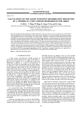
Fig. 1. Schematic and the coordinate system oxyz of a SCCRA.
The outline of the paper is written as follows: Sec. 2 gives the expression for the effective reflection area. In Sec. 3, the expression of the optical path difference due to dihedral offsets of every CCR is analyzed in detail. Section 4 gives the formulae for LID reflected by the SCCRA. In Sec. 5 computer simulations are applied to get the LID of the SCCRA by taking CryoSat-LRR-01 used in the satellite CryoSat as an example. Section 6 gives the conclusion.
2. GEOMETRICAL OPTICS PERFORMANCE
A SCCRA is made up of multiple CCRs whose centers of bottom surfaces are on the same sphere. The schematic and the coordinate system oxyz of a SCCRA are shown in Fig. 1. The original point o of oxyz coincides with the center point of the sphere.
The positional relationship of an arbitrary CCR; in the SCCRA and the coordinate system oxyz is shown in Fig. 2. It is necessary to declare that the CCR whose bottom surface is circle, as shown in Fig. 2. In order to help the reader understand the relationship between the coordinates easily, the CCR shape is selected as circle. The bottom shape is not limited to circle in the formulae derivation. In fact, the specific bottom shape is not involved in the derivation.
Taking the vertex of CCR; as the origin oi and three edges as o^i, o^i, oizii axes the coordinate system oxyz of CCRi is established. In order to analyze the relationship between the coordinate system oxyz and oixiyizi conveniently, the auxiliary coordinate system
o'i x' y'z' is established too. The origin point o' and the center point of CCRi bottom surface are superposed.
Ji Rc
Fig. 2. Relationship of the coordinate system oixiyizi of CCRi and the coordinate system oxyz of the SCCRA.
It is obvious that the length of oo' equals the radius of the sphere shown in Fig. 1. The length of oo' is labeled as Rm. The direction of axis o'z' is along the straight line op]. The axes o\x' and o'y' are in the plane of CCRi bottom surface, and the axis o\y' is in the plane determined by axis o'iz\ and axis olzi.
It is assumed that the coordinate of o' in the SCCRA coordinate system oxyz is (x , y , z ). The angle be-
o' o' o'
tween oo' and the axis oz is labeled as at, and the angle
between ox and the projective vector of oo' in the xoy
plane is labeled as p^ The coordinate of o' in the coordinate system oxyz can be written as (x , y , z ) =
o o o
= (Rm sin ai cos P, , Rm sin at sin p(-, Rm cos ai). The line of the intersection between plane o'oz and x'o'y' is
o'q, and the intersection angle between o'x' and o'q is labeled as . In order to accomplish the transformation from oxyz to o\x\y\z\, we take four steps. Firstly,
move the origin point o to the point o'. Secondly, rotate P, around axis oz. Thirdly, rotate ai around axis oy. Finally, rotate -yt around axis oz. Referring to the coordinate system transformation matrix [15], the rotational transformation matrix from oxyz to o'iX'iy'iZ'i is given by
Ma =
' cos at cos ß;- cos y t + sin at sin y t - cos at sin ß;- cos y t + cos ß;- sin y t sin at cos y t ^ - cos ai cos ß;- sin yt + sin ß;- cos yt sin at sin ß;- sin yt + cos ß;- cos yt - sin a;- sin yt - sin ai sin ß;- sin at sin ß;- cos at
y
x
Z(Z')
Assuming the intersection point between the plane
x'iüiy'i and the axes olxi, oyt, oz is Tix, Tiy, and Tiz respectively. The length of the three line segments otTix, oTy and o[Tiz are labeled as a which is expressed as
a = -J3h and h is the distance from the bottom surface
to the vertex of the CCR/. o' in the coordinate system
otxyz is shown as o'-xyz = (a/3, a/3, a/3), and the rotary transformation matrix from coordinate system
oix'y'zi to oxy Zi is given by
Ma =
(-J2/2 -/6/6 V3/3 '
V2/2 V6/6 -/3/3
0 76/3 V3/3
(2)
Figure 3 gives the work schematic of the SCCRA as a cooperative target for RLR. The light emitted from the receiving plane is reflected by the SCCRA. The reflected light reaches the receiving plane after a COS. The received coordinate system OXYZ is established, shown in Fig. 3. The direction of axis OZ is along the ray oO, O is the original point of OXYZ. Axis OY is in the plane determined by axis oz and OZ. The input light vector is along the negative direction of OZ, 9 and 9 is the incident angle and the azimuth angle of input light respectively.
The rotary transformation matrix from coordinate system OXYZ to oxyz is
(
Mo =
sin 9 - cos 9 cost cos 9 sin 9cos 0 0 sin 0
cos 9 sin 0 - sin 9 sin(
cos I
(3)
An auxiliary coordinate system OX' Y 'Z' is established to facilitate analysis. The origin O ' is closely to
the SCCRA. Axis OZ coincides with the axis OZ, and the axes O'X' and O'Y' parallels to the axes OX and OY respectively. The length of oO is slightly larger than the radius Rm of the SCCRA. Considering the distance between the receiving plane and the SCCRA is far greater than the size of the SCCRA, the wave-front of input light is assumed as a plane before entering into the SCCRA, and coinciding with the plane X'O' Y . The input light vector is L' = (0,0, -1) in the O'X'Y'Z' coordinate system. An arbitrary light PQ among the input lights is set
Для дальнейшего прочтения статьи необходимо приобрести полный текст. Статьи высылаются в формате PDF на указанную при оплате почту. Время доставки составляет менее 10 минут. Стоимость одной статьи — 150 рублей.